- Catalogs
- Silicon Laboratories
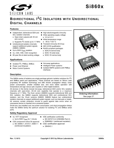
- Si473x-B20 BROADCAST MULTI-BAND RADIO RECEIVER
Si473x-B20 BROADCAST MULTI-BAND RADIO RECEIVER

Si473x-B20 BROADCAST MULTI-BAND RADIO RECEIVER
The Si473x series are integrated multiband radio receiver ICs supporting FM, AM, SW, LW, and weather bands. They minimize external components and require no factory alignment, reducing the receiver footprint by over 90% compared to traditional solutions. Key features include advanced seek algorithms, auto-calibrated digital tuning, FM stereo processing, and a programmable reference clock.
Operating conditions include a supply voltage range of 2.7 to 5.5 V and an interface supply voltage of 1.5 to 3.6 V. The devices function within an ambient temperature range of -20 to 85°C. Exceeding absolute maximum ratings may cause permanent damage.
The FM receiver supports frequencies from 76 to 108 MHz, with a sensitivity of 2.2 µV EMF for headphone networks. It offers high audio output voltage and stereo separation, with a typical audio mono S/N ratio of 63 dB.
AM band supports 520 to 1710 kHz, SW supports 2.3 to 21.85 MHz, and LW supports 153 to 279 kHz. Sensitivity is 25 µV EMF, with a power supply rejection ratio of 40 dB.
The weather band operates between 162.4 and 162.55 MHz, with a sensitivity of 0.9 µV EMF and an adjacent channel selectivity of 52 dB.
The Si473x series is suitable for various applications including table and portable radios, audio video receivers, stereos, mini/micro systems, CD/DVD players, portable media players, cellular handsets, emergency radios, clock radios, modules, mini HiFi, and boom boxes.
The reference clock supports frequencies between 31.130 kHz and 40 MHz, with a frequency tolerance of ±100 ppm. The crystal oscillator operates at 32.768 kHz with a tolerance of ±50 ppm, crucial for FM seek/tune operations.
Guidelines for integrating the Si473x series into an AM/FM application include placing capacitors close to the VDD pin, connecting all grounds to the PCB ground plane, and ensuring short traces for FMI and AMI connections. Optional components for digital audio output and crystal oscillator are also mentioned.
Lists components required for the Si473x application, including capacitors, resistors, and optional components like transformers and antennas. Suppliers for each component are provided.
Details the functions of each pin on the Si473x-GM, including RF inputs, reset, serial data inputs, and audio outputs. Specific connections for FM and AM antennas are highlighted.
Lists available Si473x models, detailing their capabilities (e.g., AM/FM, RDS/RBDS support) and operating temperature range. The package type is QFN, and all models are Pb-free.
Dimensions for the Si473x QFN package and PCB land pattern are specified, following ANSI Y14.5M-1994 standards. Recommendations for solder mask design and stencil design are included to ensure optimal assembly.
References to additional resources such as compliance test certificates and programming guides are provided for further information.
Contact details for Silicon Laboratories are provided for further inquiries or support.
Catalog excerpts

Rev. 0.5 10/08 Copyright © 2008 by Silicon Laboratories Si473x-B20 Si473x-B20 BROADCAST MULTI-BAND RADIO RECEIVER Features Applications Si473x Product Selector Guide ƒÞ FM band support: 76–108 MHz ƒÞ AM band support: 520–1710 kHz ƒÞ SW band support: 2.3–21.85 MHz (Si4734/35) ƒÞ LW band support: 153–279 kHz (Si4734/35) ƒÞ Weather band support: 162.4– 162.55 MHz (Si4736/37/38/39) ƒÞ 1050 Hz alert tone detection (Si4736/37/38/39) ƒÞ Excellent real-world performance ƒÞ Freq synthesizer with integrated VCO ƒÞ Advanced seek tuning ƒÞ Automatic frequency control (AFC) ƒÞ Automatic gain control (AGC) ƒÞ Integrated LDO regulator ƒÞ Digital FM stereo decoder ƒÞ Programmable de-emphasis ƒÞ Adaptive noise suppression ƒÞ AM/FM digital tuning ƒÞ EN55020 compliant ƒÞ No manual alignment necessary ƒÞ Programmable reference clock ƒÞ Volume control ƒÞ Programmable soft mute control ƒÞ RDS/RBDS processor (Si4731/35/37/39) ƒÞ Optional digital audio output (Si4731/35/37/39) ƒÞ 2-wire control interface ƒÞ 2.7 to 5.5 V supply voltage ƒÞ Firmware upgradeable ƒÞ Wide range of ferrite loop sticks and air loop antennas supported ƒÞ 3 x 3 x 0.55 mm 20-pin QFN package ƒÜ Pb-free/RoHS compliant ƒÞ Table and portable radios ƒÞ Audio video receivers ƒÞ Stereos ƒÞ Mini/micro systems ƒÞ CD/DVD players ƒÞ Portable media players ƒÞ Cellular handsets ƒÞ Emergency radios ƒÞ Clock radios ƒÞ Modules ƒÞ Mini HiFi ƒÞ Boom boxes Part FM AM RDS SW/LW WB Si4730 76 – 108 MHz „Ï Si4731 76 – 108 MHz „Ï „Ï Si4734 64 – 108 MHz „Ï „Ï Si4735 64 – 108 MHz „Ï „Ï „Ï Si4736 76 – 108 MHz „Ï „Ï Si4737 76 – 108 MHz „Ï „Ï „Ï Si4738 76 – 108 MHz „Ï Si4739 76 – 108 MHz „Ï „Ï Patents Pending Notes: 1. Place Si473x as close as possible to antenna jack and keep the FMI and AMI traces as short as possible. 2. Contact your local sales representatives for more information or to obtain application notes. Ordering Information: See page 18. Pin Assignments GND PAD 1 2 3 20 19 18 17 11 12 13 14 6 7 8 9 4 5 16 10 15 GPO2/INT VIO DOUT LOUT ROUT RST GND NC AMI RCLK SDIO VDD FMI RFGND GPO3/DCLK NC GPO1 DFS SCLK SEN Si473x-GM (Top View)
Open the catalog to page 1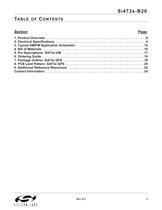
Si473x-B20 Rev. 0.5 3 TABLE OF CONTENTS Section Page 1. Product Overview . . . . . . . . . . . . . . . . . . . . . . . . . . . . . . . . . . . . . . . . . . . . . . . . . . . . . . . . .4 2. Electrical Specifications . . . . . . . . . . . . . . . . . . . . . . . . . . . . . . . . . . . . . . . . . . . . . . . . . . .4 3. Typical AM/FM Application Schematic . . . . . . . . . . . . . . . . . . . . . . . . . . . . . . . . . . . . . . .15 4. Bill of Materials . . . . . . . . . . . . . . . . . . . . . . . . . . . . . . . . . . . . . . . . . . . . . . . . . . . . . . . . . .16 5. Pin Descriptions:...
Open the catalog to page 3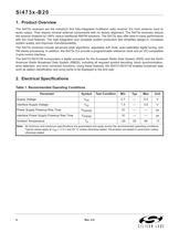
Si473x-B20 4 Rev. 0.5 1. Product Overview The Si473x receivers are the industry's first fully-integrated multiband radio receiver ICs from antenna input to audio output. They require minimal external components with no factory alignment. The Si473x receivers reduce the receiver footprint by >90% versus traditional AM/FM solutions. The Si473x also offer best-in-class performance with the most features. The high integration and complete system production test simplifies design-in, increases system quality, and improves manufacturability. The Si473x receivers include advanced seek algorithms, adjustable...
Open the catalog to page 4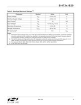
Si473x-B20 Rev. 0.5 5 Table 2. Absolute Maximum Ratings1,2 Parameter Symbol Value Unit Supply Voltage VDD –0.5 to 5.8 V Interface Supply Voltage VIO –0.5 to 3.9 V Input Current3 IIN 10 mA Input Voltage3 VIN –0.3 to (VIO + 0.3) V Operating Temperature TOP –40 to 95 „aC Storage Temperature TSTG –55 to 150 „aC RF Input Level4 0.4 VPK Notes: 1. Permanent device damage may occur if the above Absolute Maximum Ratings are exceeded. Functional operation should be restricted to the conditions as specified in the operational sections of this data sheet. Exposure beyond recommended operating conditions...
Open the catalog to page 5
Si473x-B20 6 Rev. 0.5 Table 3. DC Characteristics (VDD = 2.7 to 5.5 V, VIO = 1.5 to 3.6 V, TA = –20 to 85 °C) Parameter Symbol Test Condition Min Typ Max Unit FM Mode Supply Current IFM — 19.2 22 mA Supply Current1 IFM Low SNR level — 19.8 23 mA RDS Supply Current2 IFM — 19.9 23 mA WB Mode (Si4736/37/38/39 only) Supply Current IFM — 19.2 22 mA Supply Current1 IFM Low SNR level — 19.8 23 mA AM Mode (Si4730/31/34/35/36/37 only) Supply Current IAM — 17.3 20.5 mA Supplies and Interface Interface Supply Current IIO — 320 600 ìA VDD Powerdown Current IDDPD — 10 20 ìA VIO Powerdown Current IIOPD SCLK,...
Open the catalog to page 6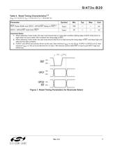
Si473x-B20 Rev. 0.5 7 Figure 1. Reset Timing Parameters for Busmode Select Table 4. Reset Timing Characteristics1,2 (VDD = 2.7 to 5.5 V, VIO = 1.5 to 3.6 V, TA = –20 to 85 °C) Parameter Symbol Min Typ Max Unit RST Pulse Width and GPO1, GPO2/INT Setup to RST„^ƒ£ tSRST 100 — — ìs GPO1, GPO2/INT Hold from RST„^ tHRST 30 — — ns Important Notes: 1. When selecting 2-wire mode, the user must ensure that a 2-wire start condition (falling edge of SDIO while SCLK is high) does not occur within 300 ns before the rising edge of RST. 2. When selecting 2-wire mode, the user must ensure that SCLK is high during...
Open the catalog to page 7All Silicon Laboratories catalogs and technical brochures
 ISOmodem Solutions Guide
2 Pages
 PRODUCT SELECTOR GUIDE 2013
36 Pages
 MCU Selector Guide
20 Pages
 Wireless and RF Selector Guide
12 Pages
 Human Interface Solutions Guide
12 Pages
 Isolation Selector Guide
10 Pages
 Microcontroller Selector Guide
20 Pages
 Audio Applications Guide
24 Pages
 USB Bridge Solutions
2 Pages
 Si4032/31/30 ISM Transmitter
2 Pages


Archived catalogs
 Broadcast Audio Solutions
2 Pages
 Digital Power Solutions
2 Pages
 Low-Voltage/Low-Power MCUs
2 Pages


- Temperature probe
- Proximity switch
- Transceiver module
- Rectangular proximity sensor
- Radio transceiver module
- Surface-mount oscillator
- IC transceiver
- Semiconductor temperature sensor
- Electromechanical oscillator
- Digital proximity sensor
- Gate driver
- Silicon temperature sensor
- Signal isolator-converter
- FM transceiver
- Infrared proximity sensor
- MOSFET gate driver
- Isolator signal isolator-converter
- IC temperature sensor
- Opto-isolated gate driver