- Catalogs
- Silicon Laboratories
- FULLY-INTEGRATED 802.3-COMPLIANT POE PD INTERFACE AND LOW-EMI SWITCHING REGULATOR
FULLY-INTEGRATED 802.3-COMPLIANT POE PD INTERFACE AND LOW-EMI SWITCHING REGULATOR
FULLY-INTEGRATED 802.3-COMPLIANT POE PD INTERFACE AND LOW-EMI SWITCHING REGULATOR
- Compliant with IEEE 802.3 standards, including legacy PoE support.
- Highly integrated with minimal external components.
- Includes integrated diode bridges, transient surge suppressor, and switching regulator with on-chip power FET.
- Programmable classification circuit and comprehensive protection circuitry.
- Supports non-isolated and isolated switching topologies.
- Low-profile 5 x 5 mm 20-pin QFN package.
- Operating voltage range: 2.8 to 57 V.
- Ambient operating temperature: -40 to 85 °C.
- Protection features include transient overvoltage protection, undervoltage lockout, and thermal shutdown.
Catalog excerpts
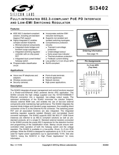
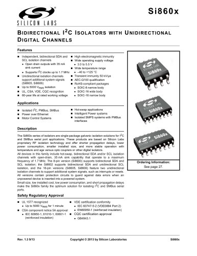
Rev. 1.1 11/10 Copyright © 2010 by Silicon Laboratories Si3402 Si3402 FULLY-INTEGRATED 802.3-COMPLIANT POE PD INTERFACE AND LOW-EMI SWITCHING REGULATOR Features Applications Description The Si3402 integrates all power management and control functions required in a Power-over-Ethernet (PoE) powered device (PD) application. The Si3402 converts the high voltage supplied over the 10/100/1000BASE-T Ethernet connection into a regulated, low-voltage output supply. The optimized architecture of the Si3402 minimizes the solution footprint, reduces external BOM cost, and enables the use of low-cost external components while maintaining high performance. The Si3402 integrates the required diode bridges and transient surge suppressor, thus enabling direct connection of the IC to the Ethernet RJ-45 connector. The switching power FET and all associated functions are also integrated. The integrated switching regulator supports isolated (flyback) and non-isolated (buck) converter topologies. The Si3402 supports IEEE Std 802.3™ 2008 (future instances are referred to as 802.3) compliant solutions as well as prestandard products, all in a single IC. Standard external resistors connected to the Si3402 provide the proper 802.3 signatures for the detection function and programming of the classification mode. Startup circuits ensure wellcontrolled initial operation of both the hotswap switch and the voltage regulator. The Si3402 is available in a low-profile, 20-pin, 5 x 5 mm QFN package. While the Si3402 is designed for applications up to 10 W, it can be used for higher power applications (up to approximately 15 W). See also “AN313: Using the Si3401/2 in High Power Applications” for more information. ƒÞ IEEE 802.3 standard-compliant solution, including pre-standard (legacy) PoE support ƒÞ Highly-integrated IC enables compact solution footprints ƒÜƒnMinimal external components ƒÜƒnIntegrated diode bridges and transient surge suppressor ƒÜƒnIntegrated switching regulator controller with on-chip power FET ƒÜƒnIntegrated dual current-limited hotswap switch ƒÞ Programmable classification circuit ƒÞ Incorporates switcher EMIreduction techniques. ƒÞ Supports non-isolated and isolated switching topologies ƒÞ Comprehensive protection circuitry ƒÜƒnTransient overvoltage protection ƒÜƒnUndervoltage lockout ƒÜƒnEarly power-loss indicator ƒÜƒnThermal shutdown protection ƒÜƒnFoldback current limiting ƒÞ Low-profile 5 x 5 mm 20-pin QFN ƒÞ RoHS-compliant ƒÞ Voice over IP telephones and adapters ƒÞ Wireless access points ƒÞ Security cameras ƒÞ Point-of-sale terminals ƒÞ Internet appliances ƒÞ Network devices ƒÞ High power applications Ordering Information: See page 19. Pin Assignments 5 x 5 mm QFN (Top View) EROUT SSFT RDET HSO RCL SP1 SP2 VPOSF CT1 PLOSS ISOSSFT VDD 5 6 7 8 9 10 20 19 18 17 16 15 1 2 3 4 11 12 13 14 VNEG VSSA VPOSS VSS1 SWO VSS2 FB VNEG (PAD) CT2
Open the catalog to page 1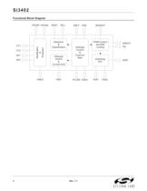
Si3402 2 Rev. 1.1 Functional Block Diagram Detection & Classification Hotswap Switch & Current limit Hotswap Control & Common Bias PWM Control and EMI Limiting Switching FET Rectification & Protection CT1 CT2 SP1 SP2 VPOSF VNEG RDET RCL HSO VDD PLOSS VSS1 SWO EROUT FB SSFT ISOSSFT VSS2 VPOSS VSSA
Open the catalog to page 2
Si3402 Rev. 1.1 3 TABLE OF CONTENTS Section Page 1. Electrical Specifications . . . . . . . . . . . . . . . . . . . . . . . . . . . . . . . . . . . . . . . . . . . . . . . . . . .4 2. Typical Application Schematics . . . . . . . . . . . . . . . . . . . . . . . . . . . . . . . . . . . . . . . . . . . . .9 3. Functional Description . . . . . . . . . . . . . . . . . . . . . . . . . . . . . . . . . . . . . . . . . . . . . . . . . . .11 3.1. Overview . . . . . . . . . . . . . . . . . . . . . . . . . . . . . . . . . . . . . . . . . . . . . . . . . . . . . . . . . .11 3.2. PD Hotswap Controller . ....
Open the catalog to page 3
Si3402 4 Rev. 1.1 1. Electrical Specifications Table 1. Recommended Operating Conditions Description Symbol Min Typ Max Units |CT1 – CT2| or |SP1 – SP2| VPORT 2.8 — 57 V Ambient Operating Temperature TA –40 25 85 °C Note: Unless otherwise noted, all voltages referenced to VNEG. All minimum and maximum specifications are guaranteed and apply across the recommended operating conditions. Typical values apply at nominal supply voltage and ambient temperature unless otherwise noted. Table 2. Absolute Maximum Ratings (DC)1 Type Description Rating Unit Voltage CT1 to CT2 –60 to 60 V SP1 to SP2 –60 to...
Open the catalog to page 4
Si3402 Rev. 1.1 5 Current RCL 0 to 100 mA RDET 0 to 1 CT1, CT2, SP1, SP2 –400 to 400 VPOS2 –400 to 400 HSO 0 to 400 PLOSS –0.5 to 5 VDD 0 to 2 SWO 0 to 400 VSS1, VSS2, or VSSA –400 to 0 Ambient Temperature Storage –65 to 150 °C Operating –40 to 85 Table 2. Absolute Maximum Ratings (DC)1 (Continued) Type Description Rating Unit Notes: 1. Unless otherwise noted, all voltages referenced to VNEG. Permanent device damage may occur if the maximum ratings are exceeded. Functional operation should be restricted to those conditions specified in the operational sections of this data sheet. Exposure to...
Open the catalog to page 5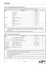
Si3402 6 Rev. 1.1 Table 3. Absolute Maximum Ratings (Transient)1 Transient surge is defined in IEC60060 as a 1000 V impulse of either polarity applied across CT1–CT2 or SP1–SP2. The shape of the impulse shall have a 300 ns full rise time and a 50 ìs half fall time, with 201 ƒÇ source impedance. Type Description Rating Unit Voltage CT1 to CT2 –82 to 82 V SP1 to SP2 –82 to 82 VPOS2 –0.7 to 80 HSO –0.7 to 80 VSS1, VSS2, or VSSA –0.7 to 80 SWO –0.7 to 80 PLOSS to VPOS2 –80 to 0.7 RDET –0.7 to 80 Current CT1, CT2, SP1, SP2 –5 to 5 A VPOS2 –5 to 5 Notes: 1. Unless otherwise noted, all voltages referenced...
Open the catalog to page 6All Silicon Laboratories catalogs and technical brochures
 ISOmodem Solutions Guide
2 Pages
 PRODUCT SELECTOR GUIDE 2013
36 Pages
 MCU Selector Guide
20 Pages
 Wireless and RF Selector Guide
12 Pages
 Human Interface Solutions Guide
12 Pages
 Isolation Selector Guide
10 Pages
 Microcontroller Selector Guide
20 Pages
 Audio Applications Guide
24 Pages
 USB Bridge Solutions
2 Pages
 Si4032/31/30 ISM Transmitter
2 Pages


Archived catalogs
 Broadcast Audio Solutions
2 Pages
 Digital Power Solutions
2 Pages
 Low-Voltage/Low-Power MCUs
2 Pages


- Temperature probe
- Proximity switch
- Transceiver module
- Rectangular proximity sensor
- Crystal oscillator
- Radio transceiver module
- Surface-mount oscillator
- IC transceiver
- Semiconductor temperature sensor
- Electromechanical oscillator
- Digital proximity sensor
- Gate driver
- Silicon temperature sensor
- Signal isolator-converter
- FM transceiver
- Infrared proximity sensor
- MOSFET gate driver
- Isolator signal isolator-converter
- IC temperature sensor
- Opto-isolated gate driver