- Catalogs
- Silicon Laboratories
- CP2108 Single-Chip USB-to-Quad-UART Bridge
CP2108 Single-Chip USB-to-Quad-UART Bridge
1 /30Pages

CP2108 Single-Chip USB-to-Quad-UART Bridge
1 /30Pages
Catalog excerpts

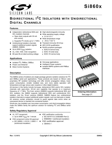
CP2108 S INGLE - C HIP USB- T O - Q U A D - U A R T B R ID G E Single-Chip USB-to-QUAD UART Data Transfer UART Interface Features independent UART interfaces Integrated USB transceiver; no external resistor required Integrated clock; no external crystal required Integrated programmable EEPROM for storing customizable product information On-chip power-on reset circuit On-chip voltage regulator: 3.3 V output Each UART interface supports the following: Supports hardware flow control (RTS/CTS) Supports all modem control signals Data formats supported: - Data bits: 5, 6, 7, and 8 - Stop bits: 1, 1.5, and 2 - Parity: odd, even, set, mark and none Baud rates: 300 bps to 2 Mbps UART 3 (pins 1–6) supports interfacing to devices up to 6V USB Peripheral Function Controller USB USB Specification 2.0 compliant; full-speed (12 Mbps) suspend states supported via SUSPEND pins GPIO Interface Features Total of 16 GPIO pins with configurable options pin support Usable as inputs, open-drain or push-pull outputs 4 configurable clock outputs for external devices RS-485 bus transceiver control Toggle LED upon transmission Toggle LED upon reception Virtual COM Port Drivers with existing COM port PC applications distribution license Windows 8/7/Vista/XP/Server 2003 Mac OS X Linux Royalty-free Package Options Supply Voltage 3.0 to 3.6 V USB bus powered: 4.0 to 5.5 V VIO voltage: 3.0 to VDD VIOHD Ordering Part Number CP2108-B02-GM CP2108 Connect to VBUS or External Supply Voltage Regulator Baud Rate Generator Handshake Control VBUS D+ D- Full-Speed 12 Mbps Transceiver Peripheral Function Controller Data FIFO 18 EEPROM (Product Customization) I/O Power and Logic Levels UART0-2, GPIO, SUSPEND, RESET VIOHD High Drive UART 3(Pins 1-6) Figure 1. Example System Diagram Copyright © 2014 by Silicon Laboratories
Open the catalog to page 1
CP2108 TABLE O F C ONTENTS Section 1. System Overview . . . . . . . . . . . . . . . . . . . . . . . . . . . . . . . . . . . . . . . . . . . . . . . . . . . . . . . . .4 2. Ordering Part Number Information . . . . . . . . . . . . . . . . . . . . . . . . . . . . . . . . . . . . . . . . . . .4 3. Electrical Specifications . . . . . . . . . . . . . . . . . . . . . . . . . . . . . . . . . . . . . . . . . . . . . . . . . . .5 3.1. Electrical Characteristics . . . . . . . . . . . . . . . . . . . . . . . . . . . . . . . . . . . . . . . . . . . . . . .5 3.2. Absolute Maximum Ratings . . . . . . . . ....
Open the catalog to page 3
CP2108 1. System Overview The CP2108 is a highly integrated USB-to-Quad-UART Bridge Controller providing a simple solution for updating RS-232/RS-485 designs to USB using a minimum of components and PCB space. The CP2108 includes a USB 2.0 full-speed function controller, USB transceiver, oscillator, EEPROM, and four asynchronous serial data buses (UART) with full modem control signals in a compact 9 x 9 mm QFN-64 package (sometimes called “MLF” or “MLP”). The on-chip EEPROM may be used to customize the USB Vendor ID (VID), Product ID (PID), Product Description String, Power Descriptor, Device...
Open the catalog to page 4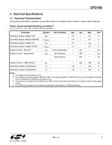
CP2108 3. Electrical Specifications 3.1. Electrical Characteristics All electrical parameters in all tables are specified under the conditions listed in Table 2, unless stated otherwise. Table 2. Recommended Operating Conditions1 VDD= 3.0 to 3.6 V, –40 to +85 °C unless otherwise specified. Operating Supply Voltage VREGIN Operating Supply Voltage VIO Operating Supply Voltage VIOHD Supply Current—Normal3 Supply Current—Suspended Operating Supply Voltage VDD Test Condition Normal Operation Self Powered Supply Current—USB Pull-up4 Operating Ambient Temperature Operating Junction Temperature Notes:...
Open the catalog to page 5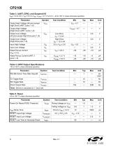
CP2108 Table 3. UART, GPIO, and Suspend I/O VDD= 3.0 to 3.6 V, VIO=1.8 V to VDD, VIOHD = 2.7 V to 6.0 V, –40 to +85 °C unless otherwise specified. Output High Voltage (All pins except High Drive UART 3 pins 1–6) Test Condition Output Low Voltage (High Drive pins 1–6) Output Low Voltage (All pins except High Drive pins 1–6) Output High Voltage (High Drive UART 3 pins 1–6) Low Drive IOL = 3 mA High Drive IOL = 12.5 mA Input High Voltage Weak Pull-up Current (VIN = 0 V) Weak Pull-up Current UART 3 (pins 1–6) Test Condition Table 4. GPIO Output Specifications –40 to +85°C unless otherwise specified....
Open the catalog to page 6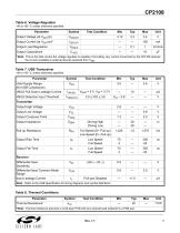
CP2108 Table 6. Voltage Regulator –40 to +85 °C unless otherwise specified. Test Condition Output Load Regulation Output Capacitance *Note: This is the total current the voltage regulator is capable of providing. Any current consumed by the CP2108 reduces the current available to external devices powered from VDD. Table 7. USB Transceiver –40 to +85 °C unless otherwise specified. Parameter Valid Supply Range (for USB Compliance) VBUS Pull-Down Leakage Current VBUS Detection Input Threshold Test Condition Transmitter Output High Voltage Output Crossover Point Output Impedance Driving High Driving...
Open the catalog to page 7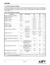
CP2108 3.2. Absolute Maximum Ratings Stresses above those listed under Table 9 may cause permanent damage to the device. This is a stress rating only and functional operation of the devices at those or any other conditions above those indicated in the operation listings of this specification is not implied. Exposure to maximum rating conditions for extended periods may affect device reliability. Table 9. Absolute Maximum Ratings Parameter Test Condition Ambient Temperature under Bias Storage Temperature GPIO/UART pins except 1–6 UART,GPIO,Suspend I/O, RESET except for UART 3 pins1–6 UART,GPIO,Suspend...
Open the catalog to page 8
CP2108 3.3. Throughput and Flow Control The throughput values in Table 10 are typical values based on bench testing and can serve as a guideline for expected performance. Other factors such as PC system performance and USB bus loading will have an effect on throughput. Each column in the table shows the typical throughput using 1, 2, 3 or all 4 UART interfaces for the set baud rate. 1. It is not necessary to use hardware flow control if all CP2108 interfaces are configured for 230,400 bps or lower. 2. For baud rates above 230,400 bps, hardware flow control should be used to guarantee reception...
Open the catalog to page 9All Silicon Laboratories catalogs and technical brochures
 ISOmodem Solutions Guide
2 Pages
 PRODUCT SELECTOR GUIDE 2013
36 Pages
 MCU Selector Guide
20 Pages
 Wireless and RF Selector Guide
12 Pages
 Human Interface Solutions Guide
12 Pages
 Isolation Selector Guide
10 Pages
 Microcontroller Selector Guide
20 Pages
 Audio Applications Guide
24 Pages
 USB Bridge Solutions
2 Pages
 Si4032/31/30 ISM Transmitter
2 Pages


Archived catalogs
 Broadcast Audio Solutions
2 Pages
 Digital Power Solutions
2 Pages
 Low-Voltage/Low-Power MCUs
2 Pages


- Liebherr temperature sensor
- Proximity switch
- Rectangular proximity sensor
- Crystal oscillator
- Radio transceiver module
- Surface-mount oscillator
- IC transceiver
- Semiconductor temperature sensor
- Electromechanical oscillator
- Digital proximity sensor
- Gate driver
- Silicon temperature sensor
- Signal isolator-converter
- FM transceiver
- Infrared proximity sensor
- MOSFET gate driver
- Isolator signal isolator-converter
- IC temperature sensor
- Opto-isolated gate driver