- Catalogs
- Silicon Designs
- Silicon Designs Model 2266 Analog Accelerometer Module

Silicon Designs Model 2266 Analog Accelerometer Module

Silicon Designs Model 2266 Analog Accelerometer Module
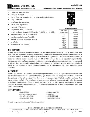
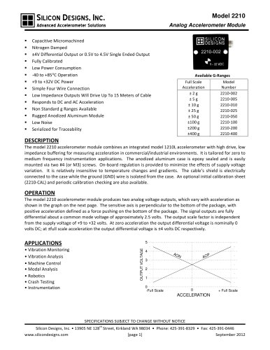
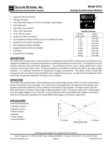
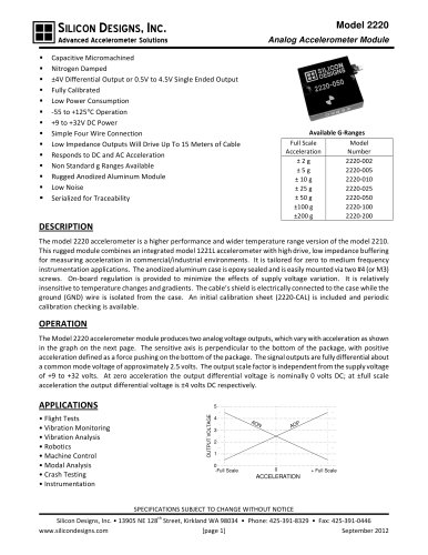
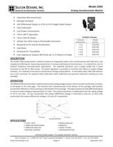
The Model 2266 accelerometer module integrates a model 1221L accelerometer with high drive, low impedance buffering, suitable for zero to medium frequency applications in commercial and industrial environments. It features an anodized aluminum case, epoxy sealing, and is mountable with screws. The module includes on-board regulation to minimize supply voltage variation effects and is relatively insensitive to temperature changes. It connects via a 5-pin connector and offers optional calibration services.
The module outputs two analog voltages that vary with acceleration. The sensitive axis is perpendicular to the package bottom, with positive acceleration defined as a force on the bottom. Outputs are differential around a 2.5V common mode voltage, with a scale factor independent of the supply voltage. At zero acceleration, the differential output is 0V DC, and at full scale, it is ±4V DC.
Applications include flight tests, vibration monitoring and analysis, machine control, modal analysis, robotics, crash testing, and instrumentation. Key features include capacitive micromachining, nitrogen damping, low power consumption, and operation from -40 to +85°C with a power supply of +8 to +32V DC.
The module is available in various models with full-scale acceleration ranges of ±2g, ±5g, ±10g, ±25g, and ±50g.
Power is supplied via red (Vs) and black (GND) wires. Green (AOP) and white (AON) wires provide analog outputs proportional to acceleration. At zero acceleration, both outputs are approximately 2.5V.
Performance varies by model, with input ranges from ±2g to ±50g and frequency responses from 0-400Hz to 0-2000Hz. Sensitivity, output noise, and mechanical shock tolerance are specified for each model. General performance parameters include cross-axis sensitivity, bias calibration error, temperature shifts, scale factor errors, and power supply rejection ratio.
The accelerometer performs best in differential mode using both AOP and AON outputs. Single-ended operation is possible but reduces the signal-to-noise ratio by half.
The cable features gold-plated brass connectors and a Teflon FEP shield. It supports lengths up to 15 meters without testing for instability. For longer lengths, check for oscillation in the 20kHz to 50kHz range. The module can drive over 600 meters of cable, but oscillation may occur between 15 and 600 meters.
Catalog excerpts
SILICON DESIGNS, INC. Model 2266 Advanced Accelerometer Solutions Analog Accelerometer Module • Capacitive Micromachined • Nitrogen Damped • ±4V Differential Output or 0.5V to 4.5V Single Ended Output • Fully Calibrated • Low Power Consumption • -40 to +85°C Operation • +8 to +32V DC Power • Simple Four Wire Snap-In Removable Connector • Responds to DC and AC Acceleration • Low Noise • Serialized for Traceability • Low Impedance Outputs Will Drive Up To 15 Meters of Cable Available G-Ranges Full Scale Model Acceleration Number ±2g 2266-002 ±5g 2266-005 ± 10 g 2266-010 ± 25 g 2266-025 ± 50 g 2266-050 DESCRIPTION The model 2266 accelerometer module combines an integrated model 1221L accelerometer with high drive, low impedance buffering for measuring acceleration in commercial/industrial environments. It is tailored for zero to medium frequency instrumentation applications. The anodized aluminum case is epoxy sealed and is easily mounted via two #4 (or M3) screws. On-board regulation is provided to minimize the effects of supply voltage variation. It is relatively insensitive to temperature changes and gradients. A removable cable 2266-CAB attaches via a 5-pin connector. An optional initial calibration sheet (2266-CAL) and periodic calibration checking are also available. OPERATION The Model 2266 accelerometer module produces two analog voltage outputs, which vary with acceleration as shown in the graph on the next page. The sensitive axis is perpendicular to the bottom of the package, with positive acceleration defined as a force pushing on the bottom of the package. The signal outputs are fully differential about a common mode voltage of approximately 2.5 volts. The output scale factor is independent from the supply voltage of +8 to +32 volts. At zero acceleration the output differential voltage is nominally 0 volts DC; at ±full scale acceleration the output differential voltage is ±4 volts DC respectively. OUTPUT VOLTAGE 5 4 AO N P AO 3 2 1 0 -Full Scale 0 + Full Scale ACCELERATION APPLICATIONS • FLIGHT TESTS • VIBRATION MONITORING • VIBRATION ANALYSIS • MACHINE CONTROL • MODAL ANALYSIS • ROBOTICS • CRASH TESTING • INSTRUMENTATION SPECIFICATIONS SUBJECT TO CHANGE WITHOUT NOTICE th Silicon Designs, Inc. • 13905 NE 128 Street, Kirkland WA 98034 • Phone: 425-391-8329 • Fax: 425-391-0446 www.silicondesigns.com [page 1] September 2012
Open the catalog to page 1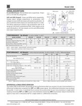
Model 2266 SIGNAL DESCRIPTIONS 0.63 [16.0] 0.48 [12.2] 0.315 [8.0] INCH [mm] 0.12 [3.0] AOP and AON (Output): Green and White wires respectively. Analog output voltages proportional to acceleration; AOP voltage increases (AON decreases) with positive acceleration. At zero acceleration both outputs are nominally equal to 2.5 volts. The device experiences positive (+1g) acceleration with its lid facing up in the Earth’s gravitational field. Either output can be used individually or the two outputs can be used differentially (see output response plot). Serial # 8 - 32 VDC XXXXX Vs and GND (Power):...
Open the catalog to page 2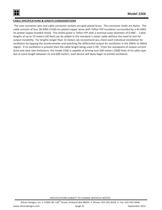
Model 2266 CABLE SPECIFICATIONS & LENGTH CONSIDERATIONS The case connector pins and cable connector sockets are gold plated brass. The connector shells are Nylon. The cable consists of four 28 AWG (7x36) tin-plated copper wires with Teflon FEP insulation surrounded by a 40 AWG tin plated copper braided shield. The shield jacket is Teflon FEP with a nominal outer diameter of 0.096”. Cable lengths of up to 15 meters (50 feet) can be added to the standard 1-meter cable without the need to test for output instability. For lengths longer than 15 meters we recommend you check each individual installation...
Open the catalog to page 3All Silicon Designs catalogs and technical brochures
 Silicon Designs Model 1010
8 Pages
 LG Series
3 Pages
 Model 3320 G-Logger
2 Pages