- Catalogs
- Silicon Designs
- Silicon Designs Model 1010

Silicon Designs Model 1010

Silicon Designs Model 1010
- Hotplate Attach Method: Use Sn62 or Sn63 solder paste, preheat to 250°C, and ensure solder flows on all pads without overheating.
- Solder Iron Attach Method: Apply solder paste or pre-tin pads, position the accelerometer, and solder opposite corner pads first to secure the part before soldering remaining connections. Allow cooling between soldering to prevent overheating.
Catalog excerpts
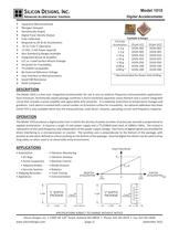
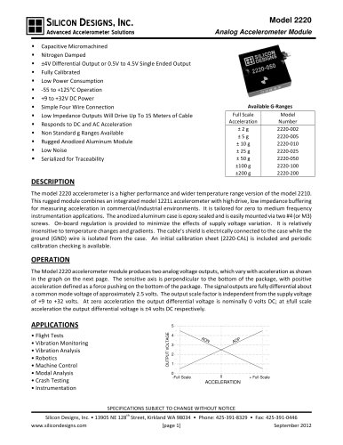
SILICON DESIGNS, INC. Advanced Accelerometer Solutions • • • • • • • • • • • • • • • • • Model 1010 Digital Accelerometer Capacitive Micromachined Nitrogen Damped Hermetically Sealed Digital Pulse Density Output Fully Calibrated Responds to DC & AC Acceleration -55 to +125 °C Operation +5 VDC, 2 mA Power (typical) Non-Standard g Ranges Available Integrated Sensor & Amplifier LCC or J-Lead Surface Mount Package Serialized for Traceability TTL/CMOS Compatible No External Reference Voltage Easy Interface to Microprocessors Good EMI Resistance RoHS Compliant Available G-Ranges Full Scale Acceleration ±2g ±5g ± 10 g ± 25 g ± 50 g ±100 g ±200 g * 20 pin LCC 1010L-002 1010L-005 1010L-010 1010L-025 1010L-050 1010L-100 1010L-200 20 pin JLCC 1010J-002 1010J-005 1010J-010 1010J-025 1010J-050 1010J-100 1010J-200 * Recommended for Down Hole Drilling DESCRIPTION The Model 1010 is a low-cost, integrated accelerometer for use in zero to medium frequency instrumentation applications. Each miniature, hermetically sealed package combines a micro-machined capacitive sense element and a custom integrated circuit that includes a sense amplifier and sigma-delta A/D converter. It is relatively insensitive to temperature changes and gradients. Each device is marked with a serial number on its bottom surface for traceability. An optional calibration test sheet (1010-TST) is also available which lists the measured bias, scale factor, linearity, operating current and frequency response. OPERATION The Model 1010 produces a digital pulse train in which the density of pulses (number of pulses per second) is proportional to applied acceleration. It requires a single +5 volt power supply and a TTL/CMOS level clock of 100kHz-1MHz. The output is ratiometric to the clock frequency and independent of the power supply voltage. Two forms of digital signals are provided for direct interfacing to a microprocessor or counter. The sensitive axis is perpendicular to the bottom of the package, with positive acceleration defined as a force pushing on the bottom of the package. External digital line drivers can be used to drive long cables or when used in an electrically noisy environment. APPLICATIONS • Automotive • Air Bags • Active Suspension • Adaptive Brakes • Security Systems • Shipping Recorders • Appliances • Vibration Monitoring • Vibration Analysis • Machine Control • Modal Analysis • Robotics • Crash Testing • Instrumentation Output Pulse Density Output Pulse Density F F FCLK /2 FCLK /2 NEGATIVE NEGATIVE ACCELERATION ACCELERATION-full -full scale 0 0 scale 0.350 "L" SUFFIX PACKAGE 0.350 Positive Acceleration 0.350 0.105 "J" SUFFIX PACKAGE +full +full scale scale POSITIVE POSITIVE ACCELERATION ACCELERATION Positive Acceleration 0.350 0.165 SPECIFICATIONS SUBJECT TO CHANGE WITHOUT NOTICE th Silicon Designs, Inc. • 13905 NE 128 Street, Kirkland WA 98034 • Phone: 425-391-8329 • Fax: 425-391-0446 www.silicondesigns.com [page 1] September 2012
Open the catalog to page 1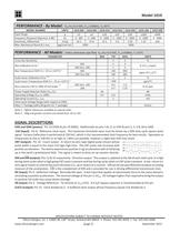
Model 1010 PERFORMANCE - By Model: VDD=VR=5.0 VDC, FCLK=250kHz, TC=25°C MODEL NUMBER UNITS 1010-002 1010-005 1010-010 1010-025 1010-050 Input Range g ±2 ±5 ±10 ±25 ±50 1 Frequency Response (Nominal, 3 dB) Hz 0 - 400 0 - 600 0 - 1000 0 - 1400 0 - 1600 2 Sensitivity, Differential mV/g 62.5 25.0 12.5 5.0 2.50 Max. Mechanical Shock (0.1 ms) μg/(root Hz) 2000 5000 PERFORMANCE - All Models: 1010-200 ±100 ±200 0 - 1800 1.25 0 - 2000 .625 Unless otherwise specified VDD=VR=5.0 VDC, FCLK=250kHz, TC=25°C PARAMETER MIN Cross Axis Sensitivity Bias Calibration Error ¹ Bias Temperature Shift (TC= -55 to +125°C)...
Open the catalog to page 2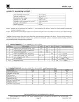
Model 1010 ABSOLUTE MAXIMUM RATINGS * Case Operating Temperature Storage Temperature Acceleration Over-range Voltage on VDD to GND 3 Voltage on Any Pin (except DV) to GND 4 Voltage on DV to GND Power Dissipation -55 to +125°C -55 to +125°C 2000g for 0.1 ms -0.5V to 6.5V -0.5V to VDD+0.5V ±15V 50 mW Note 3: Voltages on pins other than DV, GND or VDD may exceed 0.5 volt above or below the supply voltages provided the current is limited to 1 mA. Note 4: The application of DV voltages higher than required to bring the output to positive full scale may cause device damage. * NOTICE: Stresses greater...
Open the catalog to page 3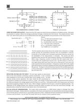
Model 1010 16 DIR 12 DIR CLK 1010x-xxx TE INPUT ST 4 CNT DV CLK/2 CO MPLE NT O DIR ME F TOUP/DO N CO W UNTE R 19 10 TOPULSECO UNTE R 15 18 (gnd) 5 17 (gnd) 6 TO VIE P W 16 DIR 15 CLK/2 8 14 VDD 9 18 RECOMMENDED CONNECTIONS (gnd) 7 CLO ÷ 2 CK CLK 6 20 1 4 10 11 12 CNT 2 G ND 5 19 2 DV 13 DIR 8 3 0.1 uF 3 VR (vdd) 100 kHz to 1 MHz 14 VDD (gnd) 11 G ND VR + 5V PINOUT (LCC & JLCC) USING THE COUNT (CNT) OUTPUT: Pulses from the CNT output are meant to be accumulated in a hardware counter. Each pulse accumulation or sample, reflects the average acceleration (change in velocity) over that interval. The...
Open the catalog to page 4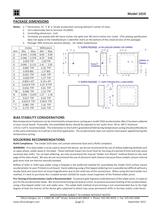
Model 1010 PACKAGE DIMENSIONS "L" SUFFIX PACKAGE (20 PIN LEADLESS CERAMIC CHIP CARRIER) *T *M C K F L E Positive Acceleration TERMINAL 20 TERMINAL 1 H J Millimeters Min Max 8.69 9.09 8.79 9.60 1.40 TYP 2.41 2.92 2.16 TYP 1.27 BSC 0.64 TYP 1.27 TYP 0.10 x 45° 0.25 R TYP 0.41 TYP 1.23 TYP 1.27 1.78 0.43 TYP 0.58 R TYP 2.16 TYP 4.45 TYP A G D "J" SUFFIX PACKAGE ("L" SUFFIC PACKAGE WITH J-LEADS ADDED) R S P B Dim A B C D E F G H J K L *M N P R *T *U Inches Min Max 0.342 0.358 0.346 0.378 0.055 TYP 0.095 0.115 0.085 TYP 0.050 BSC 0.025 TYP 0.050 TYP 0.004 x 45° 0.010 R TYP 0.016 TYP 0.048 TYP 0.050...
Open the catalog to page 5
Model 1010 Hotplate Attach Method using Solder Paste or Solder Wire: Apply solder to the circuit board’s pads using Sn62 or Sn63 solder paste or pre-tin the pads using solder and a fine tipped soldering iron. If pre-tinning with an iron, apply flux to the tinned pads prior to placing the components. Place the accelerometer in its proper position onto the pasted or tinned pads then place the entire assembly onto a hotplate that has been pre-heated to 250°C. Leave on hotplate only long enough for the solder to flow on all pads (DO NOT OVERHEAT!) Solder Iron Attach Method using Solder Paste: Apply...
Open the catalog to page 6All Silicon Designs catalogs and technical brochures
 LG Series
3 Pages
 Model 3320 G-Logger
2 Pages