Catalog excerpts

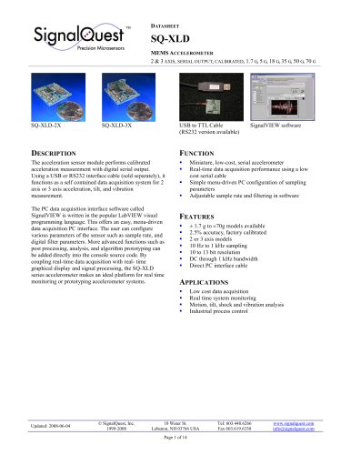
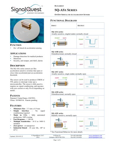
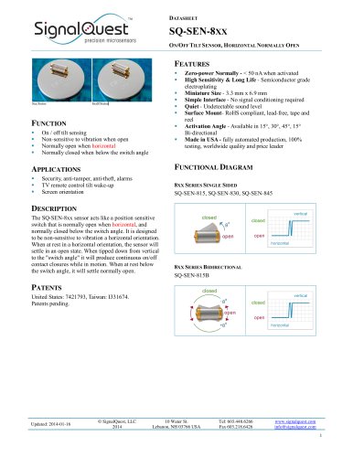
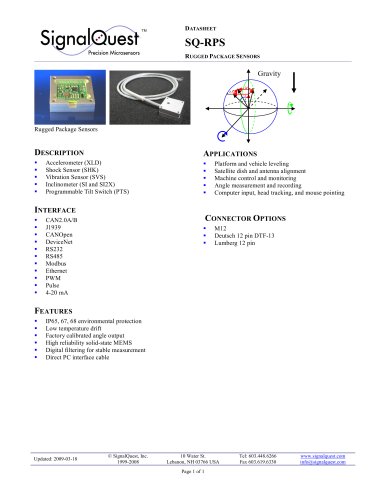
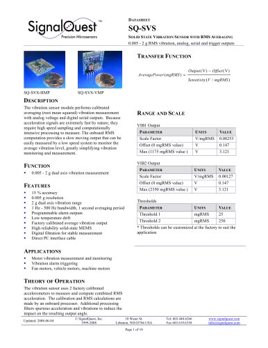
SQ-XLD MEMS ACCELEROMETER 2 & 3 AXIS, SERIAL OUTPUT, CALIBRATED, 1.7 G, 5 G, 18 G, 35 G, 50 G, 70 G USB to TTL Cable (RS232 version available) SignalVIEW software The acceleration sensor module performs calibrated acceleration measurement with digital serial output. Using a USB or RS232 interface cable (sold separately), it functions as a self contained data acquisition system for 2 axis or 3 axis acceleration, tilt, and vibration measurement. The PC data acquisition interface software called SignalVIEW is written in the popular LabVIEW visual programming language. This offers an easy, menu-driven data acquisition PC interface. The user can configure various parameters of the sensor such as sample rate, and digital filter parameters. More advanced functions such as post processing, analysis, and algorithm prototyping can be added directly into the console source code. By coupling real-time data acquisition with real- time graphical display and signal processing, the SQ-XLD series accelerometer makes an ideal platform for real time monitoring or prototyping accelerometer systems. Miniature, low-cost, serial accelerometer Real-time data acquisition performance using a low cost serial cable Simple menu-driven PC configuration of sampling parameters Adjustable sample rate and filtering in software FEATURES ± 1.7 g to ±70g models available 2.5% accuracy, factory calibrated 2 or 3 axis models 10 Hz to 1 kHz sampling 10 to 13 bit resolution DC through 1 kHz bandwidth Direct PC interface cable APPLICATIONS Low cost data acquisition Real time system monitoring Motion, tilt, shock and vibration analysis Industrial process control 10 Water St. Lebanon, NH 03766 USA Page 1 of 14 www.signalquest.com info@signalquest.com
Open the catalog to page 1
SQ-XLD MEMS ACCELEROMETER 2 & 3 AXIS, SERIAL OUTPUT, CALIBRATED, 1.7 G, 5 G, 18 G, 35 G, 50 G, 70 G 10 Water St. Lebanon, NH 03766 USA Page 2 of 14 www.signalquest.com info@signalquest.com
Open the catalog to page 2
SQ-XLD MEMS ACCELEROMETER 2 & 3 AXIS, SERIAL OUTPUT, CALIBRATED, 1.7 G, 5 G, 18 G, 35 G, 50 G, 70 G ABSOLUTE MAXIMUM RATINGS PARAMETER Voltage on +Vcc Voltage on any input pin Peak-to-peak supply noise Operating temperature Shock survivability with respect to GND with respect to GND Note: Exposure to conditions outside of the Absolute Maximum Ratings may damage the device. Prolonged exposure to conditions at the Absolute Maximum Ratings may result in degraded performance of the device over time. ELECTRICAL CHARACTERISTICS [Test conditions: 3.3v regulator, 25 º C unless otherwise specified]...
Open the catalog to page 3
SQ-XLD MEMS ACCELEROMETER 2 & 3 AXIS, SERIAL OUTPUT, CALIBRATED, 1.7 G, 5 G, 18 G, 35 G, 50 G, 70 G SIGNAL NAME UART Transmit UART Receive NC +Vcc Supply NC NC NC NC NC Digital Output – UART transmit line. Push-pull (not open collector). If not used, solder to open circuit for mechanical stability. Do not connect to GND or current drain will increase. Digital Input – UART receive line. If not used, solder to V+. Solder to open circuit for mechanical stability. Do not connect to GND Solder to open circuit for mechanical stability. Do not connect to GND Solder to open circuit for mechanical...
Open the catalog to page 4
Precision Microsensors 2 & 3 AXIS, SERIAL OUTPUT, CALIBRATED, 1.7 G, 5 G, 18 G, 35 G, 50 G, 70 G Uertical Mount Package CUMP) Horizontal Mount Package (HHP) Froni Uieu Side Uieu Side Uieu TT , J. 9AA0 ri4 © SignalQuest, Inc. 10 Water St. Tel: 603.448.6266 www.signalquest.com
Open the catalog to page 5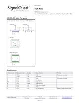
Signa [Quest™ Precision Microsensors 2 & 3 AXIS, SERIAL OUTPUT, CALIBRATED, 1.7 G, 5 G, 18 G, 35 G, 50 G, 70 G Horizontal Mount Package CHMP Dim2) TT , J. 9AA0 ri4 © SignalQuest, Inc. 10 Water St. Tel: 603.448.6266 www.signalquest.com
Open the catalog to page 6
SQ-XLD MEMS ACCELEROMETER 2 & 3 AXIS, SERIAL OUTPUT, CALIBRATED, 1.7 G, 5 G, 18 G, 35 G, 50 G, 70 G Since the device is a subassembly of surface mount components, it is not suitable for automatic assembly or wave soldering. Hand soldering of pins or SMT pads is specified for 3 seconds at 218 ºC. Pins labeled NC (no connect) should be soldered to open connection pads / pins for mechanical stability. The designer should test the device’s output voltage through its entire desired angle range during prototyping to ensure that it is working properly in the application. The device can be mounted...
Open the catalog to page 7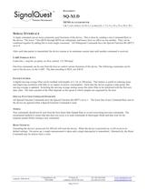
SQ-XLD MEMS ACCELEROMETER 2 & 3 AXIS, SERIAL OUTPUT, CALIBRATED, 1.7 G, 5 G, 18 G, 35 G, 50 G, 70 G SERIAL INTERFACE A single command can set most commonly-used functions of the device. This is done by sending a new Command Byte to the device. The lower 7 bits (BIT6 through BIT0) are orthogonal, and hence, have no effect on one another. They can be combined together by adding bits to form single command. All Orthogonal Commands have the Special Function Bit (BIT7) set to 0. After each data packet is transmitted, the device returns to its minimum current state until another command is...
Open the catalog to page 8
SQ-XLD MEMS ACCELEROMETER 2 & 3 AXIS, SERIAL OUTPUT, CALIBRATED, 1.7 G, 5 G, 18 G, 35 G, 50 G, 70 G Device reset Example: Acquire 1 packet as fast as possible – Combine Interrogate Mode (0x01) and Average 0 (0x00). To do this, send 0x01. The response will be 1 data packet after a delay of 1/Sample Rate seconds. Moving average length set to 100 points Moving average length set to 10 points Moving average length set to 2 points No moving average filtering Filter Control Special Commands Output Control COMMAND BYTE Reserved for future use Reserved for future use Reserved for future use...
Open the catalog to page 9
SQ-XLD MEMS ACCELEROMETER 2 & 3 AXIS, SERIAL OUTPUT, CALIBRATED, 1.7 G, 5 G, 18 G, 35 G, 50 G, 70 G SERIAL PACKET FORMAT X Acceleration (high byte) X Acceleration (low byte) Y Acceleration (high byte) Z Acceleration (high byte) Checksum (high) Format: 16-bit, unsigned integer. Output_Value = Acceleration (g)*1000. For example, a measured acceleration of 0.851 g results in an output value of 851. If no Z axis is present, the values are undefined. Format: 16-bit, unsigned integer sum of the 16 bit unsigned integer payload values. The checksum does not include the two sync bytes (0xFE 0xFE)....
Open the catalog to page 10All SignalQuest catalogs and technical brochures
-
SQ-SEN-815B
8 Pages
-
SQ-SEN-645B
8 Pages
-
SQ-GIX
13 Pages
-
SQ-RPS
1 Pages
-
SQ - ASX
8 Pages
-
SQ - SEN - 8 XX
8 Pages
-
SQ-SVS MEMS Vibration Sensor
10 Pages
-
SQ-SI-360DA MEMS Inclinometer
13 Pages
-
SQ-SEN-8xx Tilt Sensor
8 Pages
-
SQ-SEN-6xx Tilt Sensor
6 Pages
-
SQ-SEN-390 Tilt Sensor
6 Pages
-
SQ-SEN-200
5 Pages

