
- Catalogs
- Siglent Technologies Co., Ltd
- Siglent Waveform Generator SDG5000 Series ServiceManual

- Company
- Products
- Catalogs
- News & Trends
- Exhibitions
Siglent Waveform Generator SDG5000 Series ServiceManual

Siglent Waveform Generator SDG5000 Series ServiceManual
This section outlines the copyright and trademark information for SIGLENT TECHNOLOGIES CO., LTD. It emphasizes that SIGLENT products are protected by patent laws and that any modifications to specifications or pricing are at the company's discretion. The document also states that SIGLENT is not liable for any incidental or consequential damages related to the use of the manual.
The SDG5000 series conforms to national and industrial standards in China, as well as ISO9001:2008 and ISO14001:2004 standards. Other international certifications are in progress.
This section provides safety precautions to prevent personal injury and damage to the instrument. It includes instructions on proper grounding, power line usage, and handling of signal wires. It also advises against operating the device in wet or explosive environments and emphasizes the importance of keeping the instrument clean and dry.
Defines terms such as DANGER, WARNING, and CAUTION, and explains symbols used on the instrument, including hazardous voltage and earth ground symbols.
This section provides a brief overview of the SDG5000 series arbitrary waveform generator, including its main features and the structure of the manual.
The SDG5000 series uses direct digital synthesis (DDS) technology to provide stable, high-precision signals. Key features include a 4.3-inch TFT color LCD display, 500MSa/s sampling rate, and multiple waveform capabilities. It supports various modulation functions and interfaces, including USB and LAN.
Describes the layout and functions of the front panel, including the power switch, LCD display, and various control keys.
Details the connectors and ports on the rear panel, such as the Ext Trig/Gate/FSK/Burst connector, USB device connector, and power socket.
The table of contents lists all sections and chapters, including specifications, quick start guide, calibration, assembly procedures, troubleshooting, and maintenance.
Chapter 1 provides detailed specifications of the SDG5000 series, including frequency characteristics and waveform types.
Chapter 2 guides users through initial setup and familiarization with the generator's features.
Chapter 3 covers calibration procedures, including performance verification and adjustment recommendations.
Chapter 4 provides instructions for disassembling and assembling the generator, including a list of required tools and modules.
Chapter 5 offers troubleshooting procedures for common issues with the main board and power supply.
Chapter 6 includes maintenance tips and contact information for further assistance.
The document is a service manual for the SDG5000 series Arbitrary Waveform Generator, detailing specifications, procedures, and maintenance guidelines.
The SDG5000 series includes models SDG5082, SDG5122, and SDG5162, with maximum output frequencies of 80MHz, 120MHz, and 160MHz respectively. All models feature two output channels, a sample rate of 500MSa/s, and a vertical resolution of 14 bits. The devices support various modulation types including AM, FM, PM, and PWM, and have a frequency counter range of 100mHz to 200MHz.
The waveform types supported include Sine, Square, Ramp, Pulse, Noise, and Arbitrary. Each model has specific frequency ranges for these waveforms, with the highest being 160MHz for Sine waves in the SDG5162 model. The document also details rise/fall times, overshoot, duty cycles, and jitter specifications.
Amplitude ranges vary with frequency, with a maximum of 10Vpp for frequencies up to 40MHz. The document specifies amplitude flatness and channel isolation, with a channel delay of less than 1ns.
The manual describes modulation capabilities for AM, FM, PM, FSK, ASK, and PWM, with modulation frequencies up to 50kHz. Sweep functions include linear/logarithmic types with a sweep time range of 1ms to 500s.
The device features a 4.3” TFT-LCD display with a resolution of 480xRGBx272. Power requirements are 100-240 VAC, with a power consumption of less than 30W. The operating temperature range is 0°C to 40°C, with a calibration cycle of one year.
This section provides instructions for preparing the generator for use, including checking accessories, connecting the power cord, and adjusting the carrying handle. It also guides users on setting output frequency, amplitude, and configuring various waveforms.
The manual includes sections on removing various components of the device, ESD precautions, required equipment, and troubleshooting steps for checking power supply and board voltages. It also provides a quick guide for general failures and maintenance recommendations.
The manual provides steps to set the output amplitude to 8Vpp using the Ampl/HLevel softkey and digital keypad. Users can also use the knob and direction keys for input.
Instructions are given to set the DC offset to 1Vdc using the Offset/LLevel softkey and digital keypad. The knob and direction keys can also be used.
The default duty cycle is 50%, adjustable between 20% and 80% for frequencies up to 50 MHz. Steps include selecting the square wave function and setting the duty cycle to 80% using the Duty softkey.
Symmetry can be adjusted from 0% to 100%. The manual details setting symmetry to 60% using the Symmetry softkey.
Instructions for generating a pulse waveform with specific parameters: 500 µs period, 100 µs width, 8 ns rise time, and 50 ns delay.
Steps to generate a noise waveform with 500mV Stdev and 1mV Mean using the Noise function.
Guidance on setting a DC voltage with +1Vdc using the Store/Recall function and DC button.
Details on outputting a built-in "exponential fall" waveform using the Arb button and Built-In softkey.
The built-in help system provides context-sensitive assistance and a list of help topics.
Includes performance verification and adjustment procedures. Calibration intervals are recommended annually, with adjustments within the interval to ensure accuracy.
Lists equipment for performance verification and adjustment, including a Digital Multimeter and Power Meter.
Details tests for DC output, AC amplitude, and frequency response verification, with specific steps and expected ranges.
Explains channel adjustment, feedback channel adjustment, self-adjustment, vertical accuracy calibration, and frequency response adjustment.
SIGLENT provides Python scripts for calibrating SDG series products, available for download.
- Python: Ensure Python 2.7 is installed along with PyVISA, PyQt4, and PyWin32 modules.
- Microsoft Office: Required for handling test reports saved as .xls files, compatible with MS Office 2003 or later.
- NI VISA: PyVISA relies on the National Instruments VISA I/O library, which can be downloaded online.
Allow the generator and test equipment to warm up for at least 30 minutes at an ambient temperature between 18°C and 28°C to ensure optimal performance.
This involves feedback channel adjustment, channel self-adjustment, and vertical accuracy calibration.
- Feedback Channel Adjustment: Connect the DMM, PC, and SDG5000 generator, then run the FeedbackAdjust.py script.
- Channel Self Adjustment: Disconnect BNC cables after feedback adjustment, select "Self Adjust" in the Test/Cal system, and follow prompts.
- Vertical Accuracy Calibration: Calibrate amplitude at low frequency using a DMM, run VertAccCalib.py script, and follow prompts.
Compensate for amplitude changes with frequency. Connect the generator to a PC and power meter, run FrqRespCalib.py, and follow prompts for adjustments.
Includes security considerations, a list of modules, required tools, and detailed disassembly procedures.
- Security Considerations: Only qualified personnel should perform disassembly. Disconnect power to avoid electric shock and ESD damage.
- Disassembly Steps: Detailed steps for removing the handle, metal shell, front cabinet, display module, and main body using a PH2 screwdriver.
Guidelines for checking the main board, channel board, and power supply. Includes ESD precautions and required equipment like a digital multimeter and oscilloscope.
Ensure the generator is grounded, check the fuse, and test voltage values at specified test points using a digital multimeter.
Ensure all connectors on the channel and main boards are properly connected. Use a digital multimeter to verify that voltage values at test points are within specified ranges. For the channel board, test points include +15V, -15V, -5V, +5V, VCC3.3V, VCC5V, VCC1.8V, VCC1.2V, FAN_12V, and PLL_3.3V, each with an error limit of ±5%. For the main board, test points include +16V, 3.3V, VCC5V, and VCC1.2V, also with an error limit of ±5%.
Check the FPGA by observing the FPGA_LED; it should blink at 1Hz. For the mainboard clock, use an oscilloscope to verify the 25MHz frequency with a stability of ±50ppm.
Ensure DSP and CPLD chips are functioning by checking the DSP_LED/CPLD_LED lights. If the lights are on, the chips are working correctly.
For no start-up, check power connections, the power button, and the fuse. For a dark screen, verify power connections and test voltages at -5V and LED_ANODE. For no response or abnormal display, check the keypad circuit board connections.
SIGLENT offers a three-year warranty for defects in materials and workmanship. For service, contact the nearest SIGLENT office. SIGLENT is not liable for indirect or consequential damages.
When shipping for service, tag the unit with owner information and required service, use the original container or ensure 4 inches of packaging material around the unit, and use static-free materials.
Contact details for SIGLENT offices in North America, Headquarters in China, and Europe are provided for service and inquiries.
Catalog excerpts

Service Manual SDG5000 Series Function/Arbitrary Waveform Generator
Open the catalog to page 1
Copyright SIGLENT TECHNOLOGIES CO., LTD. All Rights Reserved. Trademark Information SIGLENT is the registered trademark of SIGLENT TECHNOLOGIES CO., LTD Declaration • SIGLENT products are protected by patent law in and outside of P.R.C. • SIGLENT reserves the right to modify or change parts of or all the specifications or pricing policies at company’s sole decision. • Information in this publication replaces all previously corresponding material. • Any way of copying, extracting or translating the contents of this manual is not allowed without the permission of SIGLENT. • SIGLENT will not be...
Open the catalog to page 3
Carefully read the following safety precautions to avoid person injury and prevent damage to the instrument or any products connected to it. To avoid potential hazards, please use the instrument as specified. Only qualified technician should perform service procedures Use Proper Power Line Use only the special power line of the instrument that approved by local state. Ground the Instrument The instrument grounds through the protective terra conductor of the power line. To avoid electric shock, the ground conductor must be connected to the earth. Make sure the instrument is grounded correctly...
Open the catalog to page 4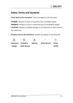
Safety Terms and Symbols Terms used on the instrument. Terms may appear on the instrument: DANGER: Indicates an injury or hazard that may immediately happen. WARNING: Indicates an injury or hazard that may not immediately happen. CAUTION: Indicates a potential damage to the instrument or other property that might occur. Symbols used on the instrument. Symbols may appear on the instrument: Hazardous Protective Warning Earth Ground Power Voltage Earth Ground Switch
Open the catalog to page 5
The document is for SDG5000 series arbitrary waveform generator, which will be mostly written as generator for short in the following text. The main contents described in this manual are: SDG5000 Series Generator at a glance This part introduces the main technology characteristics for SDG5000 generator. The Front Panel at a glance This part introduces briefly all the buttons and the knob on the front panel. The Rear Panel at a glance This part introduces all the ports for easy communication on the rear panel. Specification Chapter 1 lists the generator’s specifications. Quick Start Chapter 2...
Open the catalog to page 6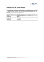
All the description for function and performance in this document are according to SDG5162 series generator, and apply to generator of the other types. The SDS5000 series contains the following types:
Open the catalog to page 7
SDG5000 Series adopt the direct digital synthesis (DDS) technology, which can provide stable, high-precision, pure and low distortion signals. Its combination of excellent system features, easiness in usage and versatile functions makes this generator a perfect solution for your testing now and in the future. Characteristics Reading the characteristics and specifications given below, you will understand how SDG5000 can satisfy your requirements. • DDS technology provides precise, stable and low distortional output signal. • 4.3inch’TFT color LCD display. • 500MSa/s sampling rate, 14-bit resolution. •...
Open the catalog to page 8
V& SIG ENT J siglent technologies simulate any complex waveform. • Remote control is realized using the USB cable. • Multiple interfaces: USB host & device. USB-GPIB (IEEE-488) and LAN (option). • Support the seamless connection with SIGLENT Series Digital Oscilloscopes; Being able to directly read and rebuild the stored waveform in the oscilloscopes. • 2 languages (English and Chinese) user interface and built-in help system. Note: All the specifications described in this manual are according to SDG5162.
Open the catalog to page 9
The Front Panel at a Glance 11 10
Open the catalog to page 10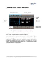
The Front Panel Display at a Glance Function Status Waveform Display Waveform Parameters Waveform type operational key Figure1 Display Interface (Sine Wave is the default waveform) Here are the character definitions in this Service Manual: The signs for buttons in this manual are the same as the panel buttons. Please note that, the signs for the functional buttons on the operation panel are represented by squared words, such as Waveforms, which represents the transparent functional key with Sine on it on the front panel, while the menu buttons are represented by brighten words such as Frequency,...
Open the catalog to page 11
The Rear Panel at a Glance 1. Ext Trig/Gate/FSK/Burst connector 2. 10MHz Output connector 3. USB Device connector 4. Power Socket 5. 10MHz Input connector 6. Sync Output connector 7. Modulation Input connector WARNING: For protection from electric shock, the grounding power cord must not be defeated. If only a two-contact electrical outlet is available, connect the instrument’s chassis ground screw (see above) to a good earth ground.
Open the catalog to page 12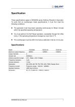
These specifications apply to SDG5000 series Arbitrary Waveform Generator. To verify that an oscilloscope meets specifications, it must first meet the following conditions: • The generator must have been operating continuously for fifteen minutes within the specified operating temperature. • You must perform the Self Adjust operation, accessible through the Utility menu, if the operating temperature changes by more than 5 °C. • The oscilloscope must be within the factory calibration interval of one year. Maximum output frequency 80MHz 120MHz 160MHz Vertical resolution 14 bits Modulation_AM,...
Open the catalog to page 15
Frequency Specification Waveform Sine, Square, Ramp, Pulse, Noise, Arbitrary waveform Accuracy within 1 year ±2ppm 0°C ~ 55°C Sine Wave Spectrum Purity Harmonic distortion Total harmonic waveform distortion Spurious signal (non-harmonic) Phase noise 100kHz Offset, -116dBc / Hz (typical value) Square Wave Asymmetric (50% Duty Cycle) Jitter (cycle to cycle) 1% of Cycle + 5 ns (typical value) < 100ps (typical value, rms) Pulse Wave_ Period Pulse width Rise/Fall time (10% ~ 90%) Duty Cycle Overshoot Jitter (cycle to cycle)
Open the catalog to page 16All Siglent Technologies Co., Ltd catalogs and technical brochures
 SDS6000A Series
21 Pages
 SDS 7000A Series
21 Pages
 SDL1000X Series
10 Pages
 SSM5000A Series
15 Pages
 Spectrum Analyzer Bandwidth
6 Pages
 Siglent_Product Catalog 2016
48 Pages
 Siglent Selection Guide 2016
10 Pages
 Benefits of deep memory
3 Pages
 SIGLENT Probes Datasheet
7 Pages
 Siglent SDS2000X User Manual
197 Pages
 Siglent SDS2000X Service Manual
59 Pages
 Probe Data Sheet + Siglent
7 Pages
 USB-GPIB User Manual_Siglent
13 Pages
 ISFE User Manual
12 Pages
 Siglent TrueArb Technology
9 Pages
 SDS2000 VS DS2000A_EN_Siglent
10 Pages
 SIGLENT SDS1000CFL
8 Pages
 SIGLENT SHS800 Data Sheet
10 Pages


- DC power supply
- AC/DC power supply
- Automation software solution
- Monitoring analyzer
- Analysis software solution
- Automatic analyser
- Windows software
- Computer-aided design software
- Cloud-based software
- Control software
- Benchtop analyser
- Design software solution
- Switched-mode power supply
- Portable analyzer
- Measurement software
- Interface software
- Real-time analyzer
- Laboratory analyzer