- Catalogs
- Siglent Technologies Co., Ltd
- Siglent Waveform Generator Productions
- Company
- Products
- Catalogs
- News & Trends
- Exhibitions
Siglent Waveform Generator Productions
1 /45Pages

Siglent Waveform Generator Productions
1 /45Pages
Catalog excerpts

Derek Song
Open the catalog to page 1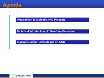
Agenda Introduction to Siglent’s AWG Products Technical Introduction of Waveform Generator Siglent’s Unique Technologies on AWG
Open the catalog to page 2
Introduction to Siglent’s AWG Products
Open the catalog to page 3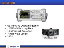
Up to 50MHz Output Frequency 125MSa/S Sampling Rate 14-bit Vertical Resolution 16kpts Wave Length 2-CH
Open the catalog to page 5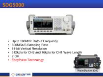
Up to 160MHz Output Frequency 500MSa/S Sampling Rate 14-bit Vertical Resolution 512kpts for CH2 and 16kpts for CH1 Wave Length 2-CH EasyPulse Technology
Open the catalog to page 6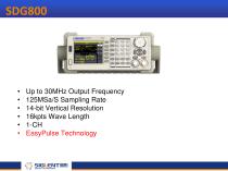
Up to 30MHz Output Frequency 125MSa/S Sampling Rate 14-bit Vertical Resolution 16kpts Wave Length 1-CH EasyPulse Technology
Open the catalog to page 7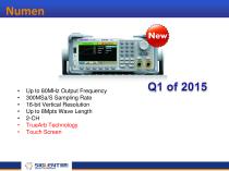
Up to 80MHz Output Frequency 300MSa/S Sampling Rate 16-bit Vertical Resolution Up to 8Mpts Wave Length 2-CH TrueArb Technology Touch Screen
Open the catalog to page 8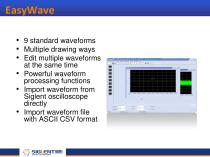
EasyWave • 9 standard waveforms • Multiple drawing ways • Edit multiple waveforms at the same time • Powerful waveform processing functions • Import waveform from Siglent oscilloscope directly • Import waveform file with ASCII CSV format
Open the catalog to page 9
Technical Introduction of Waveform Generator •Applications •Classification •Specifications and Functions
Open the catalog to page 10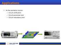
Applications • As the excitation source – Circuit verification – Circuit parameter test – Circuit redundancy test
Open the catalog to page 11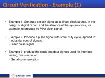
Circuit Verification - Example (1) • Example 1: Generate a clock signal as a circuit clock source, in the design of digital circuit, and the absence of the system clock, for example, to produce 10 MHz clock signal. • Example 2: Produce a pulse signal with small duty cycle, applied to: - Industrial control signals - Laser pulse signal • Example 3: produce the clock and data signals used for interface testing, bus simulation. - Serial communication
Open the catalog to page 12
Circuit Verification - Example (2) • Example 4: produce signals with a phase difference – Power system simulation – Phase discriminator • Example 5: in the switching power supply design, need to produce a pulse with a specific duty cycle as a gate control signal • Example 6: in the design of brainwave detector, need to produce characteristic brainwave signals of all sorts of diseases
Open the catalog to page 13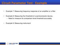
Circuit Parameter Test - Example • Example 7: Measuring frequency response of an amplifier or a filter • Example 8: Measuring the threshold of a semiconductor device – Need to measure its comparison level threshold accurately • Example 9: Measuring instrument
Open the catalog to page 14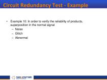
Circuit Redundancy Test - Example • Example 10: In order to verify the reliability of products, superposition in the normal signal – Noise – Glitch – Abnormal
Open the catalog to page 15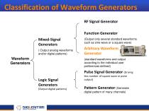
Classification of Waveform Generators RF Signal Generator Function Generator Mixed-Signal Generators ( Output analog waveforms and/or digital patterns) Waveform Generators (Output only several standard waveforms such as sine wave or a square wave) Arbitrary Waveform Generator (standard waveforms and output according to the individual user preferences defined) Pulse Signal Generator (Driving Logic Signal Generators (Output digital patterns) less number of square wave or pulse output) Pattern Generator (Generate digital pattern of many channels)
Open the catalog to page 16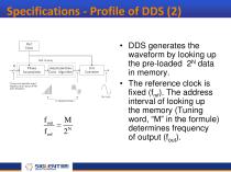
• DDS generates the waveform by looking up the pre-loaded 2N data in memory. • The reference clock is fixed (fref). The address interval of looking up the memory (Tuning word, “M” in the formule) determines frequency of output (fout).
Open the catalog to page 18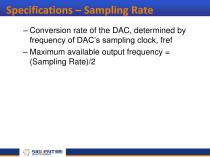
Specifications – Sampling Rate – Conversion rate of the DAC, determined by frequency of DAC’s sampling clock, fref – Maximum available output frequency = (Sampling Rate)/2
Open the catalog to page 19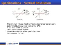
Specifications – Vertical Resolution • The minimum voltage step that the signal generator can program • Determined by binary word width of the DAC 8 bit : Step = 1/256 of full scale 14bit : Step = 1/4096 of full scale • Higher vertical noise, lower quantizing noise SQR = 6.02b + 1.76dB
Open the catalog to page 20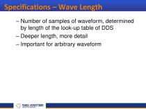
Specifications – Wave Length – Number of samples of waveform, determined by length of the look-up table of DDS – Deeper length, more detail – Important for arbitrary waveform
Open the catalog to page 21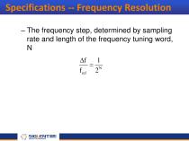
Specifications -- Frequency Resolution – The frequency step, determined by sampling rate and length of the frequency tuning word, N f 1 N f ref 2
Open the catalog to page 22
Specifications -- Frequency Range – The frequency range of sine wave – Lower limit determined by the frequency resolution – Upper limit determined by sampling rate and bandwidth of the analog channel
Open the catalog to page 23
Specifications – Frequency Accuracy – The deviation between the displayed value and the true value, usually expressed with the relative error, 1ppm = 1/1,000,000 – Determined by frequency accuracy of the time base oscillator • Generic crystal: ±(25 ~ 100) ppm • TCXO: ±(0.1 ~ 10) ppm • OCXO: ±(0.001 ~ 1) ppm
Open the catalog to page 24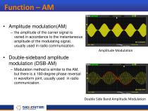
Function – AM • Amplitude modulation(AM) – the amplitude of the carrier signal is varied in accordance to the instantaneous amplitude of the modulating signal, usually used in radio communication. Amplitude Modulation • Double-sideband amplitude modulation (DSB-AM) – Modulation method is similar to the AM, but there is a 180-degree phase reversal in waveform joint, usually used in radio communication. Double Side Band Amplitude Modulation
Open the catalog to page 25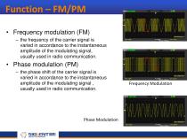
Function – FM/PM • Frequency modulation (FM) – the frequency of the carrier signal is varied in accordance to the instantaneous amplitude of the modulating signal, usually used in radio communication. • Phase modulation (PM) – the phase shift of the carrier signal is varied in accordance to the instantaneous amplitude of the modulating signal , usually used in radio communication. Phase Modulation Frequency Modulation
Open the catalog to page 26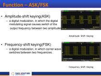
Function – ASK/FSK • Amplitude-shift keying(ASK) – a digital modulation, in which the digital modulating signal causes switch of the output frequency between two amplitudes. Amplitude Shift Keying • Frequency-shift keying(FSK) – a digital modulation, in which carrier wave switches between two frequencies. Frequency Shift Keying
Open the catalog to page 27All Siglent Technologies Co., Ltd catalogs and technical brochures
 SDS6000A Series
21 Pages
 SDS 7000A Series
21 Pages
 SDL1000X Series
10 Pages
 SSM5000A Series
15 Pages
 Spectrum Analyzer Bandwidth
6 Pages
 Siglent_Product Catalog 2016
48 Pages
 Siglent Selection Guide 2016
10 Pages
 Benefits of deep memory
3 Pages
 SIGLENT Probes Datasheet
7 Pages
 Siglent SDS2000X User Manual
197 Pages
 Siglent SDS2000X Service Manual
59 Pages
 Probe Data Sheet + Siglent
7 Pages
 USB-GPIB User Manual_Siglent
13 Pages
 ISFE User Manual
12 Pages
 Siglent TrueArb Technology
9 Pages
 SDS2000 VS DS2000A_EN_Siglent
10 Pages
 SIGLENT SDS1000CFL
8 Pages
 SIGLENT SHS800 Data Sheet
10 Pages


- EMA DC power supply
- EMA AC/DC power supply
- Automation software solution
- Monitoring analyzer
- Analysis software solution
- Automatic analyser
- Windows software
- Computer-aided design software
- Cloud-based software
- Control software
- Benchtop analyser
- Switching power supply
- Design software solution
- Portable analyzer
- Interface software
- Measurement software
- Tabletop power supply
- Real-time analyzer