
- Catalogs
- Siglent Technologies Co., Ltd
- Siglent SDS2000X Service Manual

- Company
- Products
- Catalogs
- News & Trends
- Exhibitions
Siglent SDS2000X Service Manual

Siglent SDS2000X Service Manual
The document outlines the copyright and trademark information for SIGLENT TECHNOLOGIES CO., LTD. It states that SIGLENT products are protected by patent law and reserves the right to modify specifications or pricing. SIGLENT is not responsible for losses related to the use of the manual.
SIGLENT guarantees that the product conforms to national and industrial standards in China, ISO9001: 2008, and ISO14001: 2004 standards.
This section provides safety precautions to avoid personal injuries and product damage, emphasizing the use of proper power cords, grounding, and avoiding operation in wet or explosive conditions. It explains the significance of safety terms and symbols used in the product.
The SDS2000X series oscilloscopes offer bandwidths from 70MHz to 300MHz, a maximum sample rate of 2GSa/s, and a record length of 140Mpts. They feature SPO technology, a digital trigger system, and support various triggering modes, with options for a built-in arbitrary waveform generator and digital channels.
Before performance verification or adjustments, functional checks, interface tests, and self-calibration are recommended. Instructions for power-on inspection, probe compensation, and recalling factory default settings are provided.
This section details checks to ensure the oscilloscope operates correctly, including power-on inspection and probe compensation, with step-by-step instructions for connecting the power cord and setting the probe attenuation switch.
This document is a service manual for the SIGLENT SDS2000X series oscilloscope, providing detailed procedures for setup, calibration, interface testing, performance verification, and troubleshooting.
The manual outlines initial setup steps, including connecting the probe to the CH1 BNC connector and the Compensation Signal Output Terminal, emphasizing the use of the AUTO Setup function for optimal waveform display.
Self-calibration is crucial for maintaining accuracy, especially with temperature changes exceeding 5°C. The procedure involves disconnecting all input channels, using the Utility button, and following on-screen prompts.
The oscilloscope includes USB Host, USB Device, LAN, and Pass/Fail interfaces, each with specific testing procedures to ensure proper functionality.
Performance tests verify the oscilloscope's specifications, including DC Gain Accuracy, Offset Accuracy, Time Base Accuracy, Trigger Delay, and Ext Trigger Delay, with detailed steps and required equipment.
Verification involves recording test results and ensuring they fall within specified limits. The document describes self-tests performed at power-on and the importance of self-calibration for maintaining specifications.
This manual provides comprehensive guidance for maintaining and verifying the performance of the SIGLENT SDS2000X series oscilloscope, ensuring accurate and reliable operation.
This document is a technical manual for the SIGLENT SDS2000X series oscilloscopes, detailing various verification and adjustment procedures to ensure optimal performance.
- Trigger Level Verification: Connect the oscilloscope to the SDG5000, set specific frequency and amplitude, and adjust the oscilloscope settings to verify trigger levels.
- Noise Floor Verification: Set the oscilloscope to various Volts/Div settings and measure the standard deviation to ensure it falls within specified limits.
- Bandwidth Verification: Connect the oscilloscope to the SMB100A with a 6dB attenuator, adjust settings, and measure peak-to-peak values across different frequency points.
- Bandwidth Limit Verification: Similar to bandwidth verification but with the bandwidth limit switched on.
- Trigger Sensitivity Verification: Test trigger sensitivity at 10 MHz and bandwidth frequency using specific settings.
- Input Impedance Verification: Measure input impedance across different coupling and impedance settings.
- AWG Verification: Test the AWG for offset accuracy, amplitude accuracy, and frequency response.
The document outlines steps for adjusting the oscilloscope using specific equipment and software, including warming up the devices, performing self-calibration, and using Python scripts for adjustments.
The document emphasizes the importance of warming up equipment before testing, using precise settings for each test, and ensuring all measurements fall within specified ranges.
Only qualified personnel should perform disassembly procedures. Disconnect power before removing or replacing modules to prevent injuries or component damage. Use proper ESD precautions to prevent damage from electrostatic discharge.
The removable modules in the SDS2000X series oscilloscopes include: Front-Panel Knobs, Rear Panel, Top Metal Cover, Rear Metal Cover, Power Supply Module, Metal Shelf and Interface Module, Main Board, Fan Module, Keypad Module, and Display Module.
Tools needed for module removal or replacement include a multifunctional screwdriver, antistatic gloves, and a custom screw hexagonal nut tool or long nose pliers.
Detailed steps are provided for removing and installing each module.
Guidelines are provided for addressing hardware failures, emphasizing the importance of disconnecting power and using ESD precautions.
To avoid ESD damage, handle circuit boards by the edges, minimize handling of static-sensitive modules, wear a grounded antistatic wrist strap, and operate in static-free areas.
Equipment needed for troubleshooting includes a digital multimeter and an oscilloscope with specific specifications.
A flowchart is provided to help locate defective subsystems or PCBs quickly.
Contact details for SIGLENT TECHNOLOGIES CO., LTD are provided for further assistance.
Catalog excerpts

Service Manual SDS2000X Series Digital Oscilloscope
Open the catalog to page 1
Guaranty and Declaration Copyright SIGLENT TECHNOLOGIES CO., LTDAll Rights Reserved. Trademark Information SIGLENT is the registered trademark of SIGLENT TECHNOLOGIES CO., LTD SIGLENT products are protected by patent law in and outside of P.R.C. SIGLENT reserves the right to modify or change parts of or all the specifications or pricing policies at company‟s sole decision. Information in this publication replaces all previously corresponding material. Any way of copying, extracting or translating the contents of this manual is not allowed without the permission of SIGLENT. SIGLENT will not be...
Open the catalog to page 3
General Safety Summary Review the following safety precautions to avoid personal injuries and prevent damages to this product or any products connected to it. To avoid potential hazards, use this product only as specified. Only qualified personnel should perform service procedures. To Avoid Fire or Personal Injuries Use Proper Power Cord. Use only the power cord specified for this product and approved by local state. Avoid Electric Shock. To avoid injuries or losses of life, do not connect or disconnectprobes or test leads while they are connected to a voltage source. Ground the Product. This...
Open the catalog to page 4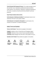
Do Not Operate With Suspected Failures. If you suspect damage occursto this instrument, have it inspected by qualified service personnel before further operation. Any maintenance, adjustment or replacement especially to the circuits or accessories should be performed by SIGLENT authorized personnel. Keep Product Surfaces Clean and Dry. Do Not Operate in Wet/Damp Conditions.To avoid electric shock, do not operate the instrument in wet or damp condition. Do Not Operate in an Explosive Atmosphere.To avoid injuries or fire hazards, do not operate in an explosive atmosphere. Safety Terms and Symbols...
Open the catalog to page 5
General Features General Features SIGLENT‟s SDS2000X series Super Phosphor Oscilloscopes are available in bandwidths of 70MHz, 100MHz, 200MHz and 300MHz, maximum sample rate of 2GSa/s, and maximum record length of 140Mpts. The most commonly used functions can be accessed with its user-friendly one-button design. The SDS2000X series employs a new generation of SPO technology. It has an innovative digital trigger system with high sensitivity and low jitter, and a maximum waveform capture rate of 140,000 wfm/s (normal mode), up to500,000 wfm/s (sequence mode). It also employs not only the common...
Open the catalog to page 9
Real-time sampling rate up to 2GSa/s New generation of SPO technology Waveform capturerateupto140,000wfm/s(normal mode),and500,000wfm/s (sequence mode) Supports 256-level intensity grading and color temperature display Record length up to 140Mpts Digital trigger system Intelligent trigger: Edge, Slope, Pulse, Window, Runt, Interval, Dropout, Pattern and Video (HDTV supported) Serial bus triggering and decode, supports protocols IIC, SPI, UART, RS232,CAN,LIN Low background noise, supports 1mV / div to 10V / div voltage scales 10 types of one-button shortcuts; supports Auto Setup, Default Setup,...
Open the catalog to page 10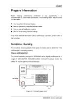
Prepare Information Before initiating performance verification or any adjustments, it is recommended to follow these procedures. The following topics are discussed in this chapter. How to perform functional checks How to operate four standard interface tests How to recall factory Default settings Fore more detailed information about oscilloscope operation, please refer to theQuick Start. Functional checking The functional checking details three types of checks used to determine if the oscilloscope is operating properly. Power-on Inspection The normal operating voltage for SDS2000X series digital...
Open the catalog to page 11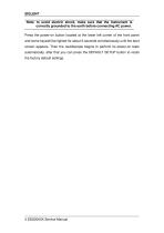
SIGLENT Note: to avoid electric shock, make sure that the instrument is correctly grounded to the earth before connecting AC power. Press the power-on button located at the lower left corner of the front panel and some keyswill be lighted for about 6 seconds simultaneously until the boot screen appears. Then the oscilloscope begins to perform its power-on tests automatically, after that you can press the DEFAULT SETUP button to recall the factory default settings.
Open the catalog to page 12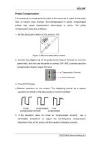
Probe Compensation It is necessary to compensate the probe at first use so as to match to the probe ratio of current input channel. Non-compensated or poorly compensated probes may cause measurement inaccuracies or errors. The probe compensation steps are as follows: 1. Set the attenuation switch on the probe to 10X. Figure 2-2Set the attenuation switch 2. Connect the alligator clip of the probe to the Ground Terminal on the front panel firstly, and then use the probe to connect CH1 BNC connector and the Compensation Signal Output Terminal. Compensation Terminal Ground Terminal 3. Press AUTO...
Open the catalog to page 13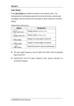
Auto Setup Press Auto Setup keyto enable the waveform auto setting function. The oscilloscope will automatically adjust the horizontal time base, vertical scale and trigger mode according to the input signal to obtain anoptimum waveform display. Table2-2Auto setting menu Option (Multi-cycle sine) Introduction Display several waveform cycles (Single-cycle sine) Display single waveform cycles (Rising edge) Display the rising edge of waveform (Falling edge) Display the falling edge of waveform (Undo Setup) Recall the previous setup of oscilloscope The input signal frequency must be higher than 20Hz,...
Open the catalog to page 14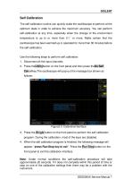
Self Calibration The self-calibration routine can quickly make the oscilloscope to perform at the optimum state in order to achieve the maximum accuracy. You can perform self-calibration at any time, especially when the change of the environment temperature is up to or more than 5 ℃ or more. Make certain that the oscilloscope has been warmed up or operated for more than 30 minutes before the self-calibration. Use the following steps to perform self calibration: 1. Disconnect all the input channels. 2. Press theUtilitybutton on the front panel,and then press theDo Self Calsoftkey.The oscilloscope...
Open the catalog to page 15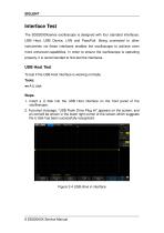
Interface Test The SDS2000Xseries oscilloscope is designed with four standard interfaces: USB Host, USB Device, LAN and Pass/Fail. Being connected to other instruments via these interfaces enables the oscilloscope to achieve even more enhanced capabilities. In order to ensure the oscilloscope is operating properly, it is recommended to first test the interfaces. USB Host Test To test if the USB Host interface is working normally. Tools: ●● A U disk Steps: 1. Insert a U disk into the USB Host interface on the front panel of the oscilloscope. 2. A prompt message, “USB Flash Drive Plug In!”,appears...
Open the catalog to page 16All Siglent Technologies Co., Ltd catalogs and technical brochures
 SDS6000A Series
21 Pages
 SDS 7000A Series
21 Pages
 SDL1000X Series
10 Pages
 SSM5000A Series
15 Pages
 Spectrum Analyzer Bandwidth
6 Pages
 Siglent_Product Catalog 2016
48 Pages
 Siglent Selection Guide 2016
10 Pages
 Benefits of deep memory
3 Pages
 SIGLENT Probes Datasheet
7 Pages
 Siglent SDS2000X User Manual
197 Pages
 Probe Data Sheet + Siglent
7 Pages
 USB-GPIB User Manual_Siglent
13 Pages
 ISFE User Manual
12 Pages
 Siglent TrueArb Technology
9 Pages
 SDS2000 VS DS2000A_EN_Siglent
10 Pages
 SIGLENT SDS1000CFL
8 Pages
 SIGLENT SHS800 Data Sheet
10 Pages


- DC power supply
- AC/DC power supply
- Automation software solution
- Monitoring analyzer
- Analysis software solution
- Automatic analyser
- Windows software
- Computer-aided design software
- Cloud-based software
- Control software
- Benchtop analyser
- Design software solution
- Switched-mode power supply
- Portable analyzer
- Measurement software
- Interface software
- Real-time analyzer
- Laboratory analyzer