
- Catalogs
- Siglent Technologies Co., Ltd
- Siglent SDS1000X/X+ Series Digital Oscilloscope User Manual

- Company
- Products
- Catalogs
- News & Trends
- Exhibitions
Siglent SDS1000X/X+ Series Digital Oscilloscope User Manual

Siglent SDS1000X/X+ Series Digital Oscilloscope User Manual
This section provides copyright and trademark information for the SIGLENT SDS1000X/SDS1000X+ Series Digital Oscilloscope, noting that SIGLENT reserves the right to modify specifications and prohibits unauthorized copying or translation of the manual.
General Safety Summary: Users should follow safety precautions to prevent injury or damage, including using the correct power line, grounding the instrument, and ensuring proper ventilation.
Safety Terms and Symbols: The manual explains safety terms and symbols, such as warnings and cautions, indicating potential hazards.
Measurement Category: The oscilloscope is suitable for measurement category I, involving circuits not directly connected to mains.
The oscilloscope should be operated within specified temperature and humidity ranges and is designed for use at altitudes below 3 km.
Proper ventilation is necessary to prevent overheating, with a recommended clearance of at least 10 cm around the device.
Instructions for cleaning the instrument and probe emphasize avoiding corrosive liquids.
This section introduces the manual's content, including quick start instructions, system settings, and troubleshooting.
The manual uses the SDS1202X+ model as an example to describe functions applicable to other models in the series.
Instructions on adjusting the vertical scale and position, specifying channel coupling, bandwidth limit, probe attenuation factor, and channel input impedance are provided for accurate waveform representation.
Guidelines for setting the horizontal system include adjusting the horizontal scale, trigger delay, and using the zoom function for detailed waveform analysis.
The document explains sampling theory, sample rate, and the relationship between oscilloscope bandwidth and sample rate, covering memory depth selection, sampling mode, waveform interpolation, and acquisition modes.
Details on setting trigger source, mode, level, coupling, holdoff, and noise rejection are included, with explanations of various trigger types.
Instructions for setting up and triggering IIC, SPI, UART/RS232, CAN, and LIN signals are provided, along with serial decode procedures for each protocol.
Guidance on connecting digital probes, acquiring waveforms, changing display types, and managing digital channels is included.
Details on performing math operations such as addition, subtraction, multiplication, division, FFT, differentiation, integration, and square root calculations are included.
Instructions for making cursor and automatic measurements, including voltage, time, and delay measurements, are provided.
Guidelines for setting display type, color, persistence, grid type, waveform intensity, and transparency are included.
Instructions for saving and recalling data internally and externally, managing disk files, and creating, deleting, or renaming files and folders are provided.
The manual begins with a quick start guide, detailing initial preparations for using the oscilloscope, including diagrams of the front and rear panels and instructions for connecting to a power supply.
Key procedures include self-calibration, enabling/disabling sound, language specification, and performing pass/fail tests.
Detailed instructions are provided for conducting self-tests and performing quick calibration and firmware updates.
The manual includes a section on using the arbitrary waveform generator, setting wave types and parameters, and outputting waveforms.
A troubleshooting section is included to help diagnose and resolve common issues.
Numerous figures illustrate various functions and settings, such as trigger menus, waveform displays, and measurement parameters.
The manual highlights features like the history function, option management, and the ability to save and recall test masks.
Inspect the shipping container for damage and verify the contents. Check the instrument for any damage or defects and notify the sales representative if issues are found.
The document provides figures showing the front and top views of the oscilloscope, with dimensions specified.
Instructions for adjusting the supporting legs, connecting to a power supply, and performing a power-on inspection are provided.
Instructions for connecting the probe to the oscilloscope and test circuit are provided, with a reference to the probe user guide for detailed technical information.
Instructions for restoring the instrument to its default configuration and using the Auto Setup function to observe waveforms are provided.
Instructions for compensating the probes to match the oscilloscope's input channels are provided.
The front panel includes an LCD display, universal knob, function menus, and various control buttons for triggering, vertical and horizontal adjustments, and more.
The rear panel features a handle, LAN and USB interfaces, a pass/fail or trigger out BNC port, AWG output terminal, safety lock hole, and AC power socket.
Details the functions of horizontal and vertical controls, including position and scale adjustments, and the use of MATH and REF functions for waveform operations.
Explains the trigger function menu, modes, and the trigger level knob for adjusting the trigger level.
Describes the auto setting function, run/stop button, decode function menu, and wave generation function.
Used for adjusting waveform intensity, selecting submenus, modifying parameters, and navigating files or directories.
Includes cursor, display, utility, clear, history, measure, acquire, save/recall, and default setup functions.
Features product logo, channel labels, trigger status, horizontal time base, trigger position, frequency counter, sampling rate/memory depth, trigger setup, and channel setup information.
The Nyquist sampling theorem states that for a band-limited signal with a maximum frequency, the sampling frequency must be greater than twice the maximum frequency to avoid aliasing.
The maximum sample rate of the oscilloscope is 2GSa/s, adjustable via the horizontal scale.
Bandwidth is the lowest frequency at which input signals are attenuated by 3 dB. The sample rate should be four times the bandwidth to reduce aliasing.
Memory depth is the number of waveform points stored in a single trigger sample, with a maximum of 14 Mpts.
The oscilloscope supports real-time sampling with a maximum rate of 1GSa/s. Interpolation methods like Sinx/X are used to improve waveform visibility.
Modes include Normal, Peak Detect, Average, and High Resolution, each offering different benefits for waveform clarity and noise reduction.
Two modes are available: YT for time-based display and XY for voltage-based display, useful for comparing frequency and phase relationships.
This mode improves waveform capture rate, allowing effective capture of small probability events by filling memory segments for each trigger event.
Trigger settings ensure stable waveform display by synchronizing acquisition with user-defined conditions. Various trigger types are available.
The document explains the trigger level settings on an oscilloscope, which can be adjusted within a range of -8 to +8 divisions.
The oscilloscope offers three trigger modes: Auto, Normal, and Single.
The trigger level can be adjusted using a knob, and the slope defines the trigger point.
Four coupling modes are available: DC, AC, LF Reject, and HF Reject.
This feature stabilizes complex waveforms by setting a holdoff time.
Noise Reject adds hysteresis to reduce noise-triggering.
The oscilloscope supports various advanced triggers, including Edge, Slope, Pulse, Video, Window, Interval, DropOut, Runt, and Pattern triggers.
This function captures waveforms of standard analog video signals.
Video triggering involves setting a trigger on a specific line and field of a video signal.
This section explains how to use a custom video trigger.
The window trigger section describes how to set up triggers based on signal levels.
This section covers interval triggers, which activate based on the time difference between signal edges.
DropOut triggers are explained with two types: edge and state.
The runt trigger section describes how to trigger on pulses that cross one threshold but not another.
This section explains pattern triggers, which identify trigger conditions based on specified patterns.
The document introduces serial trigger and decode capabilities for protocols like IIC, SPI, UART/RS232, CAN, and LIN.
Instructions for setting up and using IIC trigger and decode features are provided.
Instructions for setting up and using SPI trigger and decode features are provided.
Instructions for setting up and using UART/RS232 trigger and decode features are provided.
Instructions for setting up and using CAN trigger and decode features are provided.
Instructions for setting up and using LIN trigger and decode features are provided.
This section describes the use of digital channels in a Mixed-Signal Oscilloscope (MSO).
Instructions for connecting digital probes to a device under test are provided.
Instructions for acquiring waveforms using digital channels are provided.
Instructions for changing display types and managing digital channels are provided.
Instructions for adjusting the logic threshold for digital channels are provided.
Instructions for configuring digital channels as a bus are provided.
Instructions for saving and displaying reference waveforms are provided.
The oscilloscope supports various math operations, including addition, subtraction, multiplication, division, differential, integral, and square root.
FFT transforms time-domain data to the frequency domain, useful for measuring harmonic components, noise characteristics, and vibration analysis.
The vertical axis can be displayed in dB or Vrms, using logarithmic and linear modes respectively.
Users can choose between Split and Full Screen display modes.
Cursors can be used to measure frequency and amplitude differences.
The oscilloscope supports differentiation, integration, and square root operations.
Cursors are used for custom voltage and time measurements.
The oscilloscope provides 36 waveform parameter measurements.
Users can adjust display type, color, persistence, grid type, waveform intensity, grid brightness, and transparency.
Infinite persistence mode allows for continuous accumulation of waveform data.
The oscilloscope offers various display settings including grid type selection, waveform intensity adjustment, and grid brightness control.
Transparency settings allow users to adjust the visibility of message boxes and menus.
The oscilloscope supports saving setups, waveforms, pictures, and CSV files to internal memory or USB devices.
This section covers system-related functions such as viewing system status, performing self-calibration, enabling/disabling sound, specifying language, and conducting pass/fail tests.
This section describes the process of verifying a waveform's compliance with specific parameters using pass/fail testing.
The procedure involves accessing the UTILITY function menu, enabling the test, selecting the source channel, setting mask parameters, and creating the mask.
Test masks can be saved to internal or external memory.
The oscilloscope supports USB and LAN connections.
Quick-Cal adjusts measurement deviations due to temperature changes.
Updates are performed via USB flash drives.
Self tests include screen, keyboard, and LED tests.
The LED test program is initiated by pressing the Run/Stop button.
To set the screen saver time, access the UTILITY function menu.
The oscilloscope supports various options for measurement needs.
This function records waveforms before pressing the Run/Stop button.
The oscilloscope includes a built-in AWG supporting various waveforms.
The Default button resets the oscilloscope to factory settings.
Common issues include a dark screen after power on and no waveform display despite signal sampling.
1. Signal Testing Issues: Connect the probe compensation signal to the problematic channel and resample the signal if necessary.
2. Voltage Amplitude Discrepancies: Verify that the channel's attenuation coefficient matches the probe's attenuation ratio.
3. Unstable Waveform Display: Ensure the trigger signal source matches the actual signal channel used.
4. No Display After Run/Stop: Check if the trigger mode is set to 'Normal' or 'Single'.
5. Ladder-like Waveform Display: Increase the horizontal time base to improve resolution.
6. USB Connection Issues: Verify IO settings in Utility.
7. USB Storage Device Recognition Issues: Ensure the USB storage device and interface are functioning properly.
Catalog excerpts
User Manual SDS1000X/SDS1000X + Series Digital oscilloscope UM0101X-E02A
Open the catalog to page 1
Copyright and Declaration Copyright SIGLENT TECHNOLOGIES CO., LTD. All Rights Reserved. Trademark Information SIGLENT is the registered trademark of SIGLENT TECHNOLOGIES CO., LTD. Declaration SIGLENT products are protected by patent law in and outside of P.R.C. SIGLENT reserves the right to modify or change parts of or all the specifications or pricing policies at company’s sole decision. Information in this publication replaces all previously corresponding material. Any way of copying, extracting or translating the contents of this manual is not allowed without the permission of SIGLENT. Product...
Open the catalog to page 3
Safety Information General Safety Summary Carefully read the following safety precautions to avoid any personal injury or damage to the instrument and any products connected to it. To avoid potential hazards, please use the instrument as specified. Use Proper Power Line Only the power cord designed for the instrument and authorized by local country could be used. Ground the Instrument The instrument is grounded through the protective earth conductor of the power line. To avoid electric shock, please make sure the instrument is grounded correctly before connecting its input or output terminals....
Open the catalog to page 4
SIGLENT Use proper Fuse Use only the specified fuse. Do Not Operate Without Covers Do not operate the instrument with covers or panels removed. Do Not Operate With Suspected Failures. If you suspect damage occurs to the instrument, have it inspected by qualified service personnel before further operations. Any maintenance, adjustment or replacement especially to circuits or accessories must be performed by SIGLENT authorized personnel. Do Not Operate in Wet Conditions. In order to avoid short circuiting to the interior of the device or electric shock, please do not operate in a humid environment....
Open the catalog to page 5
Safety Terms and Symbols Terms in this Manual. These terms may appear in this manual: WARNING Warning statements indicate the conditions or practices that could result in injury or loss of life. CAUTION Caution statements indicate the conditions or practices that could result in damage to this product or other property. Terms on the product. These terms may appear on the product: DANGER Indicates direct injuries or hazards that may happen. WARNING Indicates potential injuries or hazards that may happen. CAUTION Indicates potential damages to the instrument or other property that may happen. Symbols...
Open the catalog to page 6
Measurement Category Measurement Categories The oscilloscopes can make measurements in measurement category I. WARNING This oscilloscope can only be used for measurements within its specified measurement categories. Measurement Category Definitions Measurement category I is for measurements performed on circuits not directly connected to MAINS. Examples are measurements on circuits not derived from MAINS, and specially protected (internal) MAINS derived circuits. In the latter case, transient stresses are variable; for that reason, the transient withstand capability of the equipment is made known...
Open the catalog to page 7
Working Environment Temperature Operating: 10℃ to +40℃ Non-operation:-20℃ to +70℃ Humidity Under +35℃:≤90% relative humidity +35℃ to +40℃: ≤60% relative humidity WARNING To avoid short circuit inside the instrument or electric shock, please do not operate in humid environment. Altitude Operating: less than 3 Km Non-operation: less than 15 Km Installation (overvoltage) Category This product is powered by mains conforming to installation (overvoltage) category II. WARNING Make sure that no overvoltage (such as that caused by thunderbolt) can reach the product, or else the operator might expose...
Open the catalog to page 8
Ventilation Requirement This oscilloscope uses fan to force cooling. Please make sure that the air intake and exhaust areas are free from obstructions and have free air. When using the oscilloscope in a bench-top or rack setting, provide at least 10 cm clearance beside, above and behind the instrument for adequate ventilation. WARNING Inadequate ventilation may cause temperature increase which would damage the instrument. So please keep the instrument well ventilated during operation and inspect the intake and fan regularly.
Open the catalog to page 9
General Care and Cleaning Care Do not store or leave the instrument in direct sunshine for long periods of time. WARNING To avoid damages to the instrument or probe, please do not leave them in fog, liquid, or solvent. Cleaning Please perform the following steps to clean the instrument and probe regularly according to its operating conditions. 1. Disconnect the instrument from all power sources, and then clean it with a soft wet cloth. 2. Clean the loose dust on the outside of the instrument and probe with a soft cloth. When cleaning the LCD, take care to avoid scarifying it. WARNING To avoid...
Open the catalog to page 10
Document Overview This manual introduces how to use the digital oscilloscope in details. Quick Start To Set the Vertical System To Set the Horizontal System To Set the Sample System To Trigger the Oscilloscope Serial Trigger and Decode To Save Reference Waveform To Make Math Operation To Make Cursor Measurements To Make Measurements Display Setting Save and Recall System Setting Arbitrary Waveform Generation Default Troubleshooting Provide information about preparations before using the instrument and a brief introduction of the instrument. Introduce the functions of the vertical system of the...
Open the catalog to page 11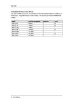
Content Conventions in this Manual: This manual takes SDS1202X+ for example and the descriptions here have contained all the functions and performances of other models. The oscilloscope includes the following models: Model Analogy Bandwidth
Open the catalog to page 12
User Manual XVII
Open the catalog to page 19
Quick Start This chapter introduces the preparations when using the oscilloscope for the first time, the front panel, rear panel and user interface of the oscilloscope, The contents of this chapter: General Inspection Front Panel Overview Rear Panel Overview Front Panel Function Overview Back Panel Function Overview User Interface
Open the catalog to page 21All Siglent Technologies Co., Ltd catalogs and technical brochures
 SDS6000A Series
21 Pages
 SDS 7000A Series
21 Pages
 SDL1000X Series
10 Pages
 SSM5000A Series
15 Pages
 Spectrum Analyzer Bandwidth
6 Pages
 Siglent_Product Catalog 2016
48 Pages
 Siglent Selection Guide 2016
10 Pages
 Benefits of deep memory
3 Pages
 SIGLENT Probes Datasheet
7 Pages
 Siglent SDS2000X User Manual
197 Pages
 Siglent SDS2000X Service Manual
59 Pages
 Probe Data Sheet + Siglent
7 Pages
 USB-GPIB User Manual_Siglent
13 Pages
 ISFE User Manual
12 Pages
 Siglent TrueArb Technology
9 Pages
 SDS2000 VS DS2000A_EN_Siglent
10 Pages
 SIGLENT SDS1000CFL
8 Pages
 SIGLENT SHS800 Data Sheet
10 Pages


- DC power supply
- AC/DC power supply
- Automation software solution
- Monitoring analyzer
- Analysis software solution
- Automatic analyser
- Windows software
- Computer-aided design software
- Cloud-based software
- Control software
- Benchtop analyser
- Design software solution
- Switched-mode power supply
- Portable analyzer
- Measurement software
- Interface software
- Real-time analyzer
- Tabletop power supply
- Laboratory analyzer