- Catalogs
- Siglent Technologies Co., Ltd
- SDS2000X Series DataSheet+Digital Oscillscope+Siglent
- Company
- Products
- Catalogs
- News & Trends
- Exhibitions
SDS2000X Series DataSheet+Digital Oscillscope+Siglent
1 /16Pages

SDS2000X Series DataSheet+Digital Oscillscope+Siglent
1 /16Pages
Catalog excerpts

Super Phosphor
Open the catalog to page 1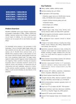
SDS2000X Series Digital Oscilloscope Real-time sampling rate up to 2GSa/s New generation of SPO technology • Waveform capture rate up to 140,000 wfm/s (normal mode), and 500,000 wfm/s (sequence mode) • Supports 256-level intensity grading and color temperature display • Record length up to 140Mpts Product Overview SIGLENT’s SDS2000X series Super Phosphor Oscilloscopes are available in bandwidths of 70MHz, 100MHz, 200MHz and 300MHz, maximum sample rate of 2GSa/s, and maximum record length of 140Mpts. The most commonly used • Digital trigger system Intelligent trigger: Edge, Slope, Pulse, Window,...
Open the catalog to page 2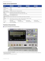
SDS2000X Series Digital Oscilloscope Models and Key Specifications Model 140 Mpts (Single-Channel), 70 Mpts (Dual-Channel) Waveform Capture Rate 140,000 wfm/s (normal mode), 500,000 wfm/s (sequence mode) (Max.) Trigger Type Edge, Slope, Pulse width, Window, Runt, Interval, Dropout, Pattern, Video Serial Trigger Decoder Type (Optional) 16 Digital Channels (MSO Maximum waveform capture rate up to 500 MSa/s, Record length up to 140 Mpts/CH Option) Wa v e f o r m G e n e r a t o r Single channel, Max. frequency up to 25MHz, 125MSa/s sampling rate, 16Kpts wave length (Optional) I/O USB Host, USB Device,...
Open the catalog to page 3
SDS2000X Series Digital Oscilloscope Functions & Characteristics Waveform Capture Rate up to 500,000wfm/s With a waveform capture rate of up to 500,000 wfm/s (sequence mode), Using hardware-based Zoom technique and record length of up to the oscilloscope can easily capture the unusual or low-probability events 140Mpts, users are able to use a higher sampling rate to capture more of the signal, and then quickly zoom in to focus on the area of interest 256-level Intensity Grading and Color Temperature Display 256-level intensity grading display on waveform Abundant Trigger Functions Color temperature...
Open the catalog to page 4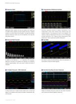
SDS2000X Series Digital Oscilloscope Segmented memory collection will store the waveform into multiple (up to 80,000) memory segments and each segment will store a triggered waveform, as well the dead time information. The dead time between segments could be as small as 2us. All the segments can be play back using History function. H Advanced Math Function In addition to the traditional (+, -, X, f) operations, FFT, integration, differential, and square root operations are supported. The integration operation supports gating, which uses cursors to define the domain of H Comprehensive Statistical...
Open the catalog to page 5
SDS2000X Series Digital Oscilloscope Built-in 25MHz Function/Arbitrary Waveform Generator (Optional) Complete Connectivity 10 built-in waveforms plus 4 ARBs. The arbitrary waveforms can be USB Host, USB Device (USBTMC), LAN(VXI-11), Pass/Fail, Trigger Out accessed and edited by the EasyWave PC software Specifications All specifications are not guaranteed unless the following conditions are met: • The oscilloscope calibration period is valid • The oscilloscope has been working continuously for at least 30 minutes at the specified temperature (18℃ ~ 28℃ ) Acquire System Sampling Rate Memory Depth...
Open the catalog to page 6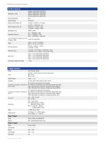
SDS2000X Series Digital Oscilloscope Vertical System Bandwidth (-3dB) Vertical Resolution Vertical Range Vertical Scale (Probe 1X) Offset Range (Probe 1X) Bandwidth Limit Bandwidth Flatness Low Frequency Response (AC ≤10Hz (at input BNC) Coupling -3dB) Noise Offset Accuracy Rise Time Overshoot (500ps Rise Edge) Trigger System Mode Auto, Normal, Single Internal: ±4.5div from the center of the screen EXT: ±0.6V EXT/5: ±3V Holdoff Range AC, DC, LFRJ, HFRJ, Noise RJ (CH1~CH4) DC: Passes all components of the signal Coupling Frequency Response AC: Blocks DC components and attenuates signals below...
Open the catalog to page 7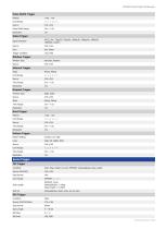
SDS2000X Series Digital Oscilloscope Pulse Width Trigger Polarity Limit Range Pulse Width Range Video Trigger Signal Standard Trigger Condition Line, Field Window Trigger Window Type Absolute, Relative Interval Trigger Slope Rising, Falling Limit Range Time Range Dropout Trigger Timeout Type Edge, State Rising, Falling Time Range Runt Trigger Polarity Limit Range Time Range Pattern Trigger Pattern Setting Limit Range Time Range Serial Trigger IIC Trigger Condition Start, Stop, Restart, No Ack, EEPROM, Address&Data, Data Length Source (SDA/SCL) Data format Limit Range Data Length EEPROM: 1byte...
Open the catalog to page 8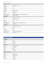
SDS2000X Series Digital Oscilloscope Start, Stop, Data, Parity Error Source (RX/TX) Data format Limit Range Data Length Data Width Parity Check Idle Level Baud Rate (Selectable) Baud Rate (Custom) All, Remote, ID, ID+Data, Error Data format Data Length Baud Rate (Selectable) Baud Rate (Custom) Break, Frame ID, ID+Data, Error Data format Data Length Baud Rate (Selectable) Baud Rate (Custom) Serial Decoder (Optional) No. of Decoder Edge Select Rising, Falling Idle Level UART/ RS232 Decoder Signal Data Width Parity Check Idle Level
Open the catalog to page 9
SDS2000X Series Digital Oscilloscope CAN_H, CAN_L CAN_H, CAN_L, CAN_H-CAN_L LIN Decoder LIN Specification Package Revision Ver1.3, Ver2.0 Threshold Measurement Source Display 5 measurements at the same time Screen, Gating Measurement Parameters (37 Types) Vmax Difference between maximum and minimum data values Difference between top and base in a bimodal signal, or between max and min in an unimodal signal Value of most probable higher state in a bimodal waveform Value of most probable lower state in a bimodal waveform Average of all data values Average of data values in the first cycle Standard...
Open the catalog to page 10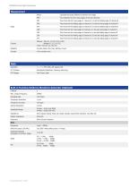
SDS2000X Series Digital Oscilloscope Measurement Phase Time between the first rising edges of the two channels Time from the first rising edge of channel A, to the first falling edge of channel B Time from the first falling edge of channel A, to the first rising edge of channel B Time from the first falling edge of channel A, to the first falling edge of channel B Time from the first rising edge of channel A, to the last rising edge of channel B Time from the first rising edge of channel A, to the last falling edge of channel B Time from the first falling edge of channel A, to the last rising...
Open the catalog to page 11All Siglent Technologies Co., Ltd catalogs and technical brochures
 SDS6000A Series
21 Pages
 SDS 7000A Series
21 Pages
 SDL1000X Series
10 Pages
 SSM5000A Series
15 Pages
 Spectrum Analyzer Bandwidth
6 Pages
 Siglent_Product Catalog 2016
48 Pages
 Siglent Selection Guide 2016
10 Pages
 Benefits of deep memory
3 Pages
 SIGLENT Probes Datasheet
7 Pages
 Siglent SDS2000X User Manual
197 Pages
 Siglent SDS2000X Service Manual
59 Pages
 Probe Data Sheet + Siglent
7 Pages
 USB-GPIB User Manual_Siglent
13 Pages
 ISFE User Manual
12 Pages
 Siglent TrueArb Technology
9 Pages
 SDS2000 VS DS2000A_EN_Siglent
10 Pages
 SIGLENT SDS1000CFL
8 Pages
 SIGLENT SHS800 Data Sheet
10 Pages


- Power supply unit
- DC power supply
- AC/DC power supply
- Automation software solution
- Monitoring analyzer
- Analysis software solution
- Automatic analyser
- Windows software
- Computer-aided design software
- Cloud-based software
- Control software
- Benchtop analyser
- Switching power supply
- Design software solution
- Portable analyzer
- Interface software
- Measurement software
- Tabletop power supply
- Real-time analyzer