- Catalogs
- Siglent Technologies Co., Ltd
- SDS1000CML+&DL+Series User Manual Siglent Ditigal Oscilloscope
- Company
- Products
- Catalogs
- News & Trends
- Exhibitions
SDS1000CML+&DL+Series User Manual Siglent Ditigal Oscilloscope
1 /126Pages

SDS1000CML+&DL+Series User Manual Siglent Ditigal Oscilloscope
1 /126Pages
Catalog excerpts

User Manual SIGLENT TECHNOLOGIES CO,.LTD
Open the catalog to page 1
Declaration Copyright © by SIGLENT TECHNOLOGIES CO,.LTD. All rights reserved. Contents in this Manual are not allowed to copy, extract and translate before being allowed by SIGLENT. User Manual
Open the catalog to page 3
Brief Introduction Characteristic: ● The volume of the oscilloscope is cabinet and it is portable ● 7” Color TFT LCD display ● 2 channels, Bandwidth: 40MHz-150 MHz ● Single real-time sampling rate is: 1Gsa/s; Equivalent sampling rate is 50GSa/s. ● Trigger types: Edge, Pulse, Video,Slope and Alternative ● Unique Digital Filter function and Waveform recorder function ● Auto measure thirty two parameters and support all measurement function. ●Two groups’ reference waveforms and twenty groups’ capture waveforms and twenty groups’ setups internal save/recall function and USB flash drive save/recall...
Open the catalog to page 4
General Safety Summary Carefully read the following safety precautions to avoid person injury and prevent damage to the instrument and any products connected to it. To avoid potential hazards, please use the instrument as specified. Only qualified technician should perform service procedures To Avoid Fire or Personal Injure Use Proper Power Line Use only the special power line of the instrument which approved by local state. Ground the Instrument The instrument grounds through the protective terra conductor of the power line. To avoid electric shock, the ground conductor must be connected to...
Open the catalog to page 5
If the equipment is used in a manner not specified by the manufacturer, the protection provided by the equipment may be impaired. This product has been tested to the requirements of CAN/CSA-C22.2 No. 61010-1, second edition, including Amendment 1, or a later version of the same standard incorporating the same level of testing requirements. Not to use the product for measurements within other measurement categories, such as CAT II, CAT III, CAT IV. Not to use the equipment for measurements on mains circuits, not to use the equipment for measurements on voltage exceed the voltage range describe...
Open the catalog to page 6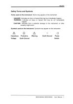
Safety Terms and Symbols Terms used on the instrument. Terms may appear on the instrument: DANGER: Indicates an injury or hazard that may be immediately happen. WARNING: Indicates an injury or hazard that may be not immediately CAUTION: Indicates that a potential damage to the instrument or other property might occur. Symbols used on the instrument. Symbols may appear on the instrument: Hazardous Protective Warning Earth Ground Power Voltage Earth Ground Switch
Open the catalog to page 7
User Manual
Open the catalog to page 9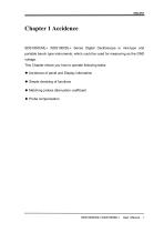
Chapter 1 Accidence SDS1000CML+ /SDS1000DL+ Series Digital Oscilloscope is mini-type and portable bench type instruments, which could be used for measuring as the GND voltage. This Chapter shows you how to operate following tasks: ◆ Accidence of panel and Display information ◆ Simple checking of functions ◆ Matching probes attenuation coefficient ◆ Probe compensation User Manu
Open the catalog to page 11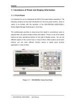
1.1 Accidence of Panel and Display Information It is important for you to understand the DSO's front panel before operating it. The following contents are the brief introduction for the front panel function, which is useful to be familiar with the operation of the SDS1000CML+/SDS1000DL+ Series Digital Storage Oscilloscope in short time. The oscilloscopes provides an easy-to-use front panel to convenience users to operate them, the panel contains knobs and buttons. There is a list of five ashen buttons as menu operational buttons on the right of display screen. You can set different options of...
Open the catalog to page 12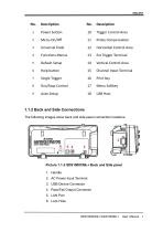
10 Trigger Control Area 12 Horizontal Control Area 14 Vertical Control Area 15 Channel Input Terminal 1.1.2 Back and Side Connections The following images show back and side panel connection locations. Picture 1.1-2 SDS1000CML+ Back and Side panel 2. AC Power Input Terminal 4. Pass/Fail Output Connector
Open the catalog to page 13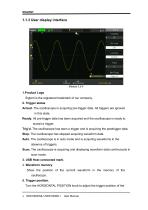
1.1.3 User display interface Siglent is the registered trademark of our company. Armed. The oscilloscope is acquiring pre-trigger data. All triggers are ignored Ready. All pre-trigger data has been acquired and the oscilloscope is ready to Trig'd. The oscilloscope has seen a trigger and is acquiring the posttrigger data. Stop. The oscilloscope has stopped acquiring waveform data. Auto. The oscilloscope is in auto mode and is acquiring waveforms in the Scan. The oscilloscope is acquiring and displaying waveform data continuously in scan mode. 3. USB Host connected mark. Show the position of the...
Open the catalog to page 14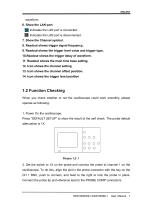
waveform. 6. Show the LAN port. Indicates the LAN port is connected. Indicates the LAN port is disconnected. 7. Show the Channel symbol. 8. Readout shows trigger signal frequency.. 9. Readout shows the trigger level value and trigger type.. 10.Readout shows the trigger delay of waveform. 11. Readout shows the main time base setting. 12. Icon shows the channel setting. 13. Icon shows the channel offset position. 14. Icon shows the trigger level position 1.2 Function Checking When you check whether or not the oscilloscope could work smoothly, please operate as following: 1. Power On the oscilloscope....
Open the catalog to page 15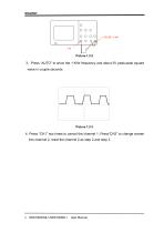
3.Press “AUTO” to show the 1 KHz frequency and about 3V peak-peak square wave in couple seconds 4. Press “CH1” two times to cancel the channel 1, Press“CH2” to change screen into channel 2, reset the channel 2 as step 2 and step 3.
Open the catalog to page 16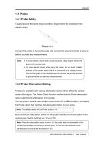
1.3 Probe 1.3.1 Probe Safety A guard around the probe body provides a finger barrier for protection from electric shock. Connect the probe to the oscilloscope and connect the ground terminal to ground before you take any measurements. Note: ● To avoid electric shock when using the probe, keep fingers behind the guard on the probe body. ● To avoid electric shock while using the probe, do not touch metallic portions of the probe head while it is connected to a voltage source. Connect the probe to the oscilloscope and connect the ground terminal to ground before you take any measurements. 1.3.2...
Open the catalog to page 17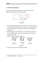
1.3.3 Probe Compensation As an alternative method to Probe Check, you can manually perform this adjustment to match your probe to the input channel. 1. Set the Probe option attenuation in the channel menu to 10X. Set the switch to 10X on the probe and connect the probe to channel 1 on the oscilloscope. If you use the probe hook-tip, ensure a proper connection by firmly inserting the tip onto the probe. 2. Attach the probe tip to the PROBE COMP~3V connector and the reference lead to the PROBE COMP Ground connector. Display the channel and then push the “AUTO” button. 3. Check the shape of the...
Open the catalog to page 18All Siglent Technologies Co., Ltd catalogs and technical brochures
 SDS6000A Series
21 Pages
 SDS 7000A Series
21 Pages
 SDL1000X Series
10 Pages
 SSM5000A Series
15 Pages
 Spectrum Analyzer Bandwidth
6 Pages
 Siglent_Product Catalog 2016
48 Pages
 Siglent Selection Guide 2016
10 Pages
 Benefits of deep memory
3 Pages
 SIGLENT Probes Datasheet
7 Pages
 Siglent SDS2000X User Manual
197 Pages
 Siglent SDS2000X Service Manual
59 Pages
 Probe Data Sheet + Siglent
7 Pages
 USB-GPIB User Manual_Siglent
13 Pages
 ISFE User Manual
12 Pages
 Siglent TrueArb Technology
9 Pages
 SDS2000 VS DS2000A_EN_Siglent
10 Pages
 SIGLENT SDS1000CFL
8 Pages
 SIGLENT SHS800 Data Sheet
10 Pages


- Power supply unit
- DC power supply
- AC/DC power supply
- Automation software solution
- Monitoring analyzer
- Analysis software solution
- Automatic analyser
- Windows software
- Computer-aided design software
- Cloud-based software
- Control software
- Benchtop analyser
- Switching power supply
- Design software solution
- Portable analyzer
- Generator
- Interface software
- Measurement software
- Tabletop power supply
- Real-time analyzer