
- Catalogs
- Siglent Technologies Co., Ltd
- SDS1000CML+&DL+Series Quick Start Siglent Ditigal Oscilloscope

- Company
- Products
- Catalogs
- News & Trends
- Exhibitions
SDS1000CML+&DL+Series Quick Start Siglent Ditigal Oscilloscope

SDS1000CML+&DL+Series Quick Start Siglent Ditigal Oscilloscope
SIGLENT TECHNOLOGIES CO., LTD. reserves the right to modify specifications and pricing. The document supersedes previous versions and prohibits unauthorized copying or translation. The product adheres to Chinese national and industrial standards, ISO9001:2008, and ISO14001:2004.
Users must adhere to safety precautions to prevent injuries and damage. Only qualified technicians should perform service procedures. The instrument must be grounded, and operation in wet or explosive environments should be avoided. Safety terms like DANGER, WARNING, and CAUTION indicate varying risk levels.
The instrument should not be exposed to direct sunlight for long periods. Cleaning involves disconnecting power and using a soft, wet cloth. Avoid corrosive liquids and ensure the instrument is dry before use.
General Inspection: Inspect the shipping container and instrument for damage. Verify accessories against the packing list.
Appearance and Dimension: Provides visual references for the oscilloscope's front and side views.
Adjust the Supporting Legs: Instructions for adjusting the legs for stable placement.
Connect to AC Power Supply: The oscilloscope accepts 100-240V AC power. Use the provided power cord.
Power-on Inspection: Instructions for turning on the oscilloscope and performing self-tests.
Connect the Probe: Details on connecting passive probes to the oscilloscope.
Function Inspection: Steps to verify the oscilloscope's functionality using default settings and observing waveforms.
Probe Compensation: Instructions for compensating the probe to ensure accurate measurements.
Describes the functions of various buttons and controls on the front panel, including power, menus, universal knob, and channel input terminals.
Describes components like the handle, AC power input, USB interface, LAN port, and lock hole.
Vertical Control: Allows adjustment of the voltage scale by turning the knob. The waveform amplitude changes accordingly, and the scale message updates on the screen. Pressing the knob switches between 'Coarse' and 'Fine' adjustment modes.
Horizontal Control: Includes options to modify the trigger position and horizontal time base. Adjusting the knob changes the waveform display and updates the time base message. The delay sweep function can be toggled, and the trigger position can be reset to zero.
Trigger Control: Supports five modes. The trigger level can be adjusted, and pressing the button sets it to the midpoint of the voltage range. The trigger can also be forced, and the level reset to the screen's vertical center.
RUN/STOP and SINGLE: The RUN/STOP button toggles the instrument state, indicated by yellow (RUN) or red (STOP) lights. The SINGLE button sets the trigger mode to 'Single'.
AUTO Function: Enables automatic waveform settings, adjusting the time base, vertical scale, and trigger mode for optimal display.
Universal Knob: Adjusts waveform brightness and can select submenus or modify parameters when the light above it is on.
Function Menus: Various menus are available for cursor measurement, acquisition settings, file management, measurement functions, display settings, and utility functions. Each menu provides specific options for detailed configuration.
DEFAULT SETUP and HELP: The DEFAULT SETUP button restores default settings, while the HELP button provides assistance for menu functions.
PRINT Function: If connected to a printer, the PRINT button enables printing of the current display.
User Interface: Includes indicators for product logo, working state, USB connection, waveform memory, trigger position, LAN connection, print function, channel identifier, frequency counter, trigger parameters, and more.
Security Lock: Instructions are provided for using a security lock to secure the instrument.
Common issues and solutions are listed, such as screen not powering on, waveform not displaying, incorrect voltage amplitude, unstable waveform, and USB storage issues. Contact information for SIGLENT is provided for unresolved problems.
Catalog excerpts
Quick Start SDS1000CML+/SDS1000DL+ Series Digital Oscilloscope QS0101A-E01B
Open the catalog to page 1
Guaranty and Declaration Copyright SIGLENT TECHNOLOGIES CO., LTD. All Rights Reserved. Trademark Information SIGLENT is the registered trademark of SIGLENT TECHNOLOGIES CO., LTD Declaration SIGLENT products are protected by patent law in and outside of P.R.C. SIGLENT reserves the right to modify or change parts of or all the specifications or pricing policies at company’s sole decision. Information in this publication replaces all previously corresponding material. Any way of copying, extracting or translating the contents of this manual is not allowed without the permission of SIGLENT....
Open the catalog to page 3
Safety Requirement General Safety Summary Carefully read the following safety precautions to avoid personal injuries and prevent damage to the instrument and any products connected to it. To avoid potential hazards, please use the instrument as specified. Only qualified technician should perform service procedures To Avoid Fire or Personal Injuries Use Proper Power Line Use only the special power line of the instrument which is approved by local state. Ground the Instrument The instrument grounds through the protective terra conductor of the power line. To avoid electric shock, the ground conductor...
Open the catalog to page 4
Do not Operate with Suspected Failures If you suspect that there is a damage of the instrument, please let a qualified service personnel check it. Avoid Circuit or Components Exposed Do not touch exposed contacts or components when the power is Do not Operate in Wet/Damp Conditions Do not Operate in an Explosive Atmosphere Keep the Surface of the Instrument Clean and Dry Safety Terms and Symbols Terms on the product. These terms may appear on the product: DANGER: Indicates direct injuries or hazards that may happen. WARNING: Indicates potential injuries or hazards that may happen. CAUTION: Indicates...
Open the catalog to page 5
General Care and Cleaning Care: Do not store or leave the instrument in direct sunshine for long periods of time. Notice: To avoid damages to the instrument or probe, please do not leave them in fog, liquid, or solvent. Cleaning: Please perform the following steps to clean the instrument and probe regularly according to its operating conditions. 1. Disconnect the instrument from all power sources, and then clean it with a soft wet cloth. 2. Clean the loose dust on the outside of the instrument and probe with a soft cloth. When cleaning the LCD, take care to avoid scarifying it. Notice: To avoid...
Open the catalog to page 6
Quick start General Inspection 1. Inspect the shipping container. Keep the damaged shipping container or cushioning material until the contents of the shipment have been completely checked and the instrument has passed both electrical and mechanical tests. The consigner or carrier will be responsible for damages to the instrument resulting from shipment. SIGLENT would not provide free maintenance or replacement. 2. Inspect the instrument. If there are instruments found damaged, defective or failure in electrical and mechanical tests, please contact SIGLENT. 3. Check the accessories. Please check...
Open the catalog to page 9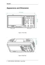
Figure 1 Front View Figure 2 Side View
Open the catalog to page 10
Adjust the Supporting Legs Adjust the supporting legs properly to use them as stands to tilt the oscilloscope upwards for stable placement as well as easier operation and observation of the instrument. Figure 3 Adjust the Supporting Legs
Open the catalog to page 11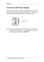
Connect to AC Power Supply The oscilloscope accept 100~240V, 50/60/440Hz AC power supply. Please use the power cord provided as accessories to connect the instrument to the power source as shown in the figure below. Power socket Note: In want of replacing the fuse, please return the instrument to the factory that produced it to have it repaired by qualified service personnel authorized by SIGLENT.
Open the catalog to page 12
Power-on Inspection When the scope is energized, press the power key at the top of it to turn it on. During the start-up progress, the instrument performs a series of self-test items and you can hear the sound of relay switching. After the self-test completes, the welcome interface displays immediately.
Open the catalog to page 13
Connect the Probe SIGLENT provides passive probes for these series oscilloscope. Please refer to corresponding Probe User Manual for detailed technical information. The following are the probes specified for this oscilloscope. Type PB470 PP510 PP215 Description 70 MHz,passive probe 100MHz, passive probe 200 MHz,passive probe Connect the probe: 1. Connect the BNC terminal of the probe to one of the channel BNC connector on the front panel. 2. Connect the probe tip to the circuit point to be tested and the ground alligator clip of the probe to the ground terminal of the circuit.
Open the catalog to page 14
Function Inspection 1. Press "Default Setup" to restore the oscilloscope to its default settings. 2. Connect the ground alligator clip of the probe to the Ground Terminal on the front panel. 3. Use the probe to connect the CH1 Input Terminal and the Compensation Signal Output Terminal on the front panel. 5. Observe waveforms on the screen. In normal condition, the display should be several square waveforms as is shown below: 6. Test channel 2 in the same method. If the square waveforms do not display like figure above, please perform "Probe Note: To avoid electric shock when using the probe,...
Open the catalog to page 15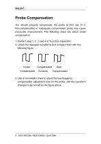
Probe Compensation You should properly compensate the probe at first use of it. Non-compensated or inadequate compensated probe may cause inaccurate measurement. The following steps are about probe compensation: 1. Perform step 1, 2 , 3 and 4 of “Function Inspection”. 2. Check the displayed waveforms and compare them with the following figure. Under Compensated Compensated Correctly Over Compensated 3. Use a nonmetallic driver to adjust the low-frequency compensation adjustment hole on the probe until the waveform changes to be correct as the figure above.
Open the catalog to page 16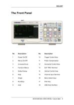
10 Trigger Control Area 12 Horizontal Control Area 14 Vertical Control Area 15 Channel Input Terminal 16 Menu Select keys
Open the catalog to page 17
1. Handle Pull up the handle vertically for easy carrying. Press it down if you do not need the handle. 2. AC Power Input Terminal The power available of the oscilloscope is 100~240V, 50/60/440Hz. Please use the power cord provided as accessories to connect the instrument to AC power. 3. USB Device Interface PC can be connected via this interface to print the current interface of the oscilloscope or control the instrument through PC software. 4. Pass/Fail Output Terminal The pass/Fail testing pulse are put out via this terminal. 5. LAN Port The oscilloscope can be controlled through the LAN port....
Open the catalog to page 18All Siglent Technologies Co., Ltd catalogs and technical brochures
 SDS6000A Series
21 Pages
 SDS 7000A Series
21 Pages
 SDL1000X Series
10 Pages
 SSM5000A Series
15 Pages
 Spectrum Analyzer Bandwidth
6 Pages
 Siglent_Product Catalog 2016
48 Pages
 Siglent Selection Guide 2016
10 Pages
 Benefits of deep memory
3 Pages
 SIGLENT Probes Datasheet
7 Pages
 Siglent SDS2000X User Manual
197 Pages
 Siglent SDS2000X Service Manual
59 Pages
 Probe Data Sheet + Siglent
7 Pages
 USB-GPIB User Manual_Siglent
13 Pages
 ISFE User Manual
12 Pages
 Siglent TrueArb Technology
9 Pages
 SDS2000 VS DS2000A_EN_Siglent
10 Pages
 SIGLENT SDS1000CFL
8 Pages
 SIGLENT SHS800 Data Sheet
10 Pages


- DC power supply
- AC/DC power supply
- Automation software solution
- Monitoring analyzer
- Analysis software solution
- Automatic analyser
- Windows software
- Computer-aided design software
- Cloud-based software
- Control software
- Benchtop analyser
- Design software solution
- Switched-mode power supply
- Portable analyzer
- Measurement software
- Interface software
- Real-time analyzer
- Tabletop power supply
- Laboratory analyzer