
- Catalogs
- Siglent Technologies Co., Ltd
- Programming Guide For SDS1000X-E Serie

- Company
- Products
- Catalogs
- News & Trends
- Exhibitions
Programming Guide For SDS1000X-E Serie

Programming Guide For SDS1000X-E Serie
This section introduces the remote communication capabilities between SIGLENT digital oscilloscopes and computers, focusing on establishing a remote control link via a communication bus.
To start programming, install the National Instruments NI-VISA library. The full version includes device drivers and NI MAX, while the Run-Time Engine is smaller. Installation involves downloading, unzipping, and following setup prompts, including accepting license agreements and potentially installing .NET Framework 4.
Oscilloscopes can connect to a PC via USB or LAN. The guide uses USB as an example. Connect the USB interfaces of the oscilloscope and PC, turn on the oscilloscope, and allow the PC to automatically install the device driver.
Users can control the oscilloscope using SCPI commands, either through user-defined programming or by sending commands via NI-VISA software.
This section details the remote control commands and queries, which can be executed in local or remote states. Commands are listed alphabetically by their long form, with descriptions including syntax and usage. Commands apply to all Siglent Digital Oscilloscope Series models, with some specific to SPO models.
Notation includes angular brackets for placeholders, colons for value descriptions, braces for choices, square brackets for optional items, and ellipses for repetition. An example command is provided for setting vertical input sensitivity.
This table lists commands and queries by short and long forms, subsystems, and their functions, such as acquisition mode, status reading, calibration, and more. Each command is associated with specific functions like acquisition, system settings, and display adjustments.
- Acquisition Commands: Commands like ACQUIRE_WAY, ARM_ACQUISITION, and AUTO_SETUP are used to control the acquisition mode, enable signal acquisition, and automatically adjust controls for waveform display.
- Status Queries: Commands such as ALL_STATUS? and CMR? provide comprehensive status information and error details.
- Channel Settings: Commands like ATTENUATION and BANDWIDTH_LIMIT adjust the vertical attenuation and bandwidth filtering of the channels.
- System Calibration: AUTO_CALIBRATE and *CAL? commands manage quick and full calibration processes.
- Communication Settings: COMM_HEADER and COMM_NET commands control response formats and network settings.
- Saving and Recalling: Commands like *SAV and STPN allow saving and recalling of device states and setups.
- Trigger Settings: Commands such as TRIG_LEVEL and TRIG_MODE adjust trigger levels and modes for signal acquisition.
- Use the *RST command to reset the device to its default state.
- Regularly perform self-calibration using the *CAL? command to ensure accurate measurements.
- Screen Functions: SCDP and SCSV manage screen dumps and screen saver settings.
- Miscellaneous Functions: BUZZER command controls sound settings, and COMM_NET manages network configurations.
- Ensure correct syntax and parameters when issuing commands to avoid errors.
- Refer to the Command Error Status Register Structure for troubleshooting syntax errors.
Description: The COUNTER command controls the display of the cymometer on the instrument screen. The COUNTER? query checks if the cymometer is displayed.
Description: The COUPLING command sets the coupling mode for a specified input channel. The COUPLING? query returns the current mode.
Description: Changes the cursor mode to auto.
Description: Specifies the cursor or parameter measurement mode.
Description: Positions cursors on the screen.
Description: Returns measured values by specified cursors.
Description: Specifies the type of cursor to display.
Description: Selects options for storing waveform in CSV format.
Description: Returns the cymometer value displayed on the instrument.
Description: Changes the oscilloscope's internal clock date/time.
Description: Reads and clears the Device Dependent Error Register.
Description: Specifies a mathematical expression for a function.
Description: Controls interpolation lines between data points.
Description: Sets the Standard Event Status Enable register.
Description: Reads and clears the Event Status Register.
1. Execution Error Register (EXR)
- Description: The EXR? query reads and clears the contents of the Execution Error Register, indicating the type of the last error detected during execution.
2. History Frame Commands
- FRAME_PARAM (FPAR?): Retrieves frame parameters including descriptor name and product name.
3. Function Filter Commands
- FILTER: Enables or disables the filter of a specified trace.
4. Math FFT Commands
- FFT_WINDOW: Selects the window for FFT.
5. Display and Zoom Commands
- GRID_DISPLAY: Selects the type of grid for display.
6. System Identification
- *IDN?: Used for identification purposes, providing information on the manufacturer, model, serial number, and firmware revision level.
This section describes how to issue an identification request to the oscilloscope using the command
*IDN?. The response provides the model and version details of the device.The
INTENSITY command adjusts the intensity level of the grid or trace on the oscilloscope, expressed as a percentage.The
INR? query reads and clears the internal state change register, which records the completion of various operations.The
INVERTSET command inverts specified traces or math waveforms.The
MENU command enables or disables the display menu.The
MATH_VERT_POS command controls the vertical position of the math waveform.The
MATH_VERT_DIV command adjusts the vertical sensitivity of the math waveform.The
MEMORY_SIZE command sets the maximum memory depth.The
MEASURE_DELAY command selects the type of delay measure between channels.The
OFFSET command adjusts the vertical offset of a specified input channel.The
*OPC command sets the OPC bit in the Event Status Register.The
PARAMETER_CLR command resets the pass/fail test counter.The
PARAMETER_CUSTOM command controls customizable measurement parameters.The
PARAMETER_VALUE? query returns measurement values for specified parameters.The
PERSIST_SETUP command sets the persistence duration of the display.The
PANEL_SETUP command archives panel setups on external storage.The
PF_DISPLAY command enables or disables the pass/fail test display.The
PF_SAVELOAD command saves or recalls mask settings.PF_SET Command: Sets the X and Y masks for pass/fail options.
*RCL Command: Recalls a panel setup.
REF_CLOSE Command: Closes the reference function.
The SCREEN_SAVE command manages the automatic screen saver for the internal color monitor, which can be set to turn off after a specified time.
The *SRE command configures the Service Request Enable register, allowing specific summary message bits in the STB register to trigger a service request.
The *STB? query reads the status register, providing the values of bits 0 to 5 and 7, and the Master Summary Status (MSS).
The STOP command halts signal acquisition immediately.
The STORE_PANEL command saves the current front-panel setup to a file on a USB device.
The SAST? query checks the acquisition status, while the SARA? query returns the sample rate.
The SET50 command sets the trigger level to the center of the signal amplitude.
The TEMPLATE? query provides a detailed description of a waveform's structure.
The trigger level can be set from -4.5DIV to 4.5DIV volts/div.
The TRIG_MODE command specifies the trigger mode, which can be AUTO, NORM, SINGLE, or STOP.
The TRIG_SELECT command selects the condition for waveform acquisition.
The TRIG_SLOPE command sets the trigger slope, which can be NEG, POS, or WINDOW.
The TRIG_WINDOW command sets the relative height of the trigger window.
The TRIG_PATTERN command sets the condition of the pattern trigger.
The UNIT command sets the unit of the specified trace, either V or A.
The VERT_POSITION command adjusts the vertical position of the FFT trace.
The VOLT_DIV command sets the vertical sensitivity in Volts/div.
The WAVEFORM? query transfers a waveform from the oscilloscope to the controller.
The WAVEFORM_SETUP command specifies the amount of data in a waveform to be transmitted.
The document provides command and query syntax for digital oscilloscopes, specifically focusing on the XY_DISPLAY command.
The document includes programming examples for controlling devices using NI-VISA library through various programming environments such as VC++, VB, MATLAB, LabVIEW, and C#.
The VC++ example outlines steps to create a project using Visual Studio and NI-VISA library.
The VB example provides a similar setup for using NI-VISA with Visual Basic 6.0.
- Environment: Win7 32bit, MATLAB R2010b
- Function: Demonstrates synchronous read and write commands to a USBTMC instrument using NI-VISA.
- Environment: Win7 32bit, LabVIEW 2011
- Function: Control devices using USBTMC and TCP/IP access.
- Environment: Win7 32bit, Visual Studio
- Function: Use NI-VISA to control devices via USBTMC or TCP/IP.
- Function: Demonstrates socket communication for device control.
Catalog excerpts
Digital Oscilloscopes Series Programming Guide Digital Oscilloscopes Series
Open the catalog to page 1
Digital Oscilloscopes Series
Open the catalog to page 2
Digital Oscilloscopes Series
Open the catalog to page 3
Digital Oscilloscopes Series Programming Overview This chapter introduces how to execute remote communications between a SIGLENT digital oscilloscope and the computer. It also introduces how to establish a remote control link over a communication bus. Build communication Install NI-VISA Before programming, you need to install National Instruments NI-VISA library, which you can download from the National Instruments web-site. Currently, NI-VISA is packaged in two versions: a full version and a Run-Time Engine version. The full version includes the NI device drivers and a tool named NI MAX that...
Open the catalog to page 4
Digital Oscilloscopes Series a.Double click the visa540_full.exe, dialog shown as below: b.Click Unzip, the installation process will automatically launch after unzipping files. If your computer needs to install .NET Framework 4, its Setup process will auto start. c.The NI-VISA installing dialog is shown above. Click Next to
Open the catalog to page 5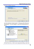
Digital Oscilloscopes Series start the installation process. Set the install path, default path is ―C:\Program Files\National Instruments\‖, you can change it. Click Next, dialog shown as above. d.Click Next twice, in the License Agreement dialog, select the
Open the catalog to page 6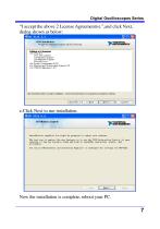
Digital Oscilloscopes Series ―I accept the above 2 License Agreement(s).‖,and click Next, dialog shown as below: e.Click Next to run installation. Now the installation is complete, reboot your PC.
Open the catalog to page 7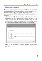
Digital Oscilloscopes Series Connect the instrument Depending on your specific model your oscilloscope may be able to communicate with a PC through the USB or LAN interface. This manual takes the USB as an example. (For instructions to communicate with a PC through the LAN interface see the User Manual.) a.Connect the USB Device interface at the rear panel of the oscilloscope and the USB Host interface of the PC using a USB cable. Assuming your PC is already turned on, turn on your oscilloscope and your PC will display the ―Device Setup‖ screen as it automatically installs the device driver as...
Open the catalog to page 8
Digital Oscilloscopes Series How To Remote Control a. User-defined Programming Users can use SCPI commands to program and control the digital oscilloscope. For details, refer to the introductions in "Programming Examples". b .Send SCPI Commands via NI-VISA You can control the oscilloscope remotely by sending SCPI commands via NI-VISA software.
Open the catalog to page 9
Digital Oscilloscopes Series About these Commands & Queries This section lists describes the remote control commands and queries recognized by the instrument. All commands and queries can be executed in either local or remote state. The description for each command or query, with syntax and other information, begins on a new page. The name (header) is given in both long and short form at the top of the page, and the subject is indicated as a command or query or both. Queries perform actions such as obtaining information, and are recognized by the question mark (?) following the header. How are...
Open the catalog to page 10
Digital Oscilloscopes Series Applicable to the following models SDS1000CML/CML+ SDS1000DL/DL+ SDS1000CNL/CNL+ SDS1000/1000X/1000X-S/1000X+/1000X-E SDS2000/SDS2000X Certain commands are only applicable to SPO oscilloscopes models and are described accordingly. SPO oscilloscopes models are in the table below. SPO models SDS1000X/1000X+/SDS1000X-E SDS2000/2000X What is an SPO model? SPO model uses Siglent-innovated waveform acquisition and graphics processing engine which supports high capture rate, multilevel intensity grading and color temperature display, with deep memory storage and the use...
Open the catalog to page 11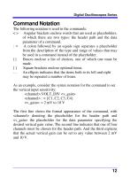
Digital Oscilloscopes Series Command Notation The following notation is used in the commands: < > Angular brackets enclose words that are used as placeholders, of which there are two types: the header path and the data parameter of a command. : = A colon followed by an equals sign separates a placeholder from the description of the type and range of values that may be used in a command instead of the placeholder. {} Braces enclose a list of choices, one of which one must be made. [ ] Square brackets enclose optional items. ... An ellipsis indicates that the items both to its left and right may...
Open the catalog to page 12
Digital Oscilloscopes Series
Open the catalog to page 13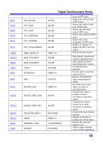
Digital Oscilloscopes Series
Open the catalog to page 15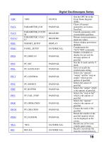
Digital Oscilloscopes Series
Open the catalog to page 16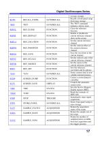
Digital Oscilloscopes Series
Open the catalog to page 17
Digital Oscilloscopes Series
Open the catalog to page 18
Digital Oscilloscopes Series
Open the catalog to page 19
Digital Oscilloscopes Series
Open the catalog to page 20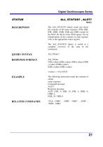
Digital Oscilloscopes Series
Open the catalog to page 21
Digital Oscilloscopes Series
Open the catalog to page 22
Digital Oscilloscopes Series Digital Oscilloscopes Series CHANNEL DESCRIPTION COMMAND SYNTAX QUERY SYNTAX RESPONSE FORMAT EXAMPLE ATTENUATION, ATTN Command /Query The ATTENUATION command selects the vertical attenuation factor of the probe. Values of 1, 5, 10, 50, 100, 500, and 1000 may be specified. The ATTENUATION? Query returns the attenuation factor of the specified channel. <channel>: ATTeNuation <attenuation> <channel> : = {C1, C2, C3, C4} <attenuation>: = {0.1, 0.2, 0.5, 1, 2, 5, 10, 20, 50, 100, 200, 500, 1000, 2000, 5000, 10000} <channel>: ATTeNuation? <channel>: ATTeNuation <attenuation> The...
Open the catalog to page 23
Digital Oscilloscopes Series
Open the catalog to page 24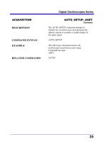
Digital Oscilloscopes Series
Open the catalog to page 25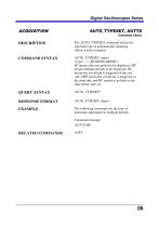
Digital Oscilloscopes Series
Open the catalog to page 26
Digital Oscilloscopes Series Digital Oscilloscopes Series ACQUISITION DESCRIPTION COMMAND SYNTAX QUERY SYNTAX RESPONSE FORMAT EXAMPLE AVERAGE_ACQUIRE, AVGA Command /Query The AVERAGE_ACQUIRE command selects the average times of average acquisition. The response to the AVERAGE_ACQUIRE query indicates the times of average acquisition. AVERAGE_ACQUIRE <time> <time> : = {4, 16, 32, 64,128,256,etc} Note: The <time> parameter’s options vary with model. AVERAGE_ACQUIRE? AVERAGE_ACQUIRE <time> The following turns the average times of average acquisition 16: Command message: AVGA 16
Open the catalog to page 27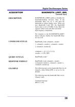
Digital Oscilloscopes Series Digital Oscilloscopes Series ACQUISITION DESCRIPTION COMMAND SYNTAX QUERY SYNTAX RESPONSE FORMAT EXAMPLE BAN DWIDTH_LIMIT, BWL Command /Query BANDWIDTH_LIMIT enables or disables the bandwidth-limiting low-pass filter. If the bandwidth filters are on, it will limit the bandwidth to reduce display noise. When you turn Bandwidth Limit ON, the Bandwidth Limit value is set to 20 MHz. It also filters the signal to reduce noise and other unwanted high frequency components. The response to the BANDWIDTH_LIMIT? Query indicates whether the bandwidth filters are on or off. BandWidth_Limit...
Open the catalog to page 28All Siglent Technologies Co., Ltd catalogs and technical brochures
 SDS6000A Series
21 Pages
 SDS 7000A Series
21 Pages
 SDL1000X Series
10 Pages
 SSM5000A Series
15 Pages
 Spectrum Analyzer Bandwidth
6 Pages
 Siglent_Product Catalog 2016
48 Pages
 Siglent Selection Guide 2016
10 Pages
 Benefits of deep memory
3 Pages
 SIGLENT Probes Datasheet
7 Pages
 Siglent SDS2000X User Manual
197 Pages
 Siglent SDS2000X Service Manual
59 Pages
 Probe Data Sheet + Siglent
7 Pages
 USB-GPIB User Manual_Siglent
13 Pages
 ISFE User Manual
12 Pages
 Siglent TrueArb Technology
9 Pages
 SDS2000 VS DS2000A_EN_Siglent
10 Pages
 SIGLENT SDS1000CFL
8 Pages
 SIGLENT SHS800 Data Sheet
10 Pages


- Power supply unit
- DC power supply
- AC/DC power supply
- Automation software solution
- Monitoring analyzer
- Analysis software solution
- Automatic analyser
- Windows software
- Computer-aided design software
- Cloud-based software
- Control software
- Benchtop analyser
- Design software solution
- Switched-mode power supply
- Portable analyzer
- Measurement software
- Interface software
- Real-time analyzer
- Tabletop power supply
- Laboratory analyzer