Catalog excerpts

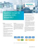
Xpedition design for reliability (DfR) Virtual HALT Benefits • Design with more than 4.5 million parts in our 3D starter library. • Visualize and immediately identify problematic parts with our simplified results. • Simulate during the design process to determine PCB reliability and reduce field failure rates. • Detect components on the threshold of failure that would be missed during physical testing. Overview Industry statistics indicate field failure rates of up to 15%-20% in the first year of newly launched electronic products, resulting in warranty claims and high levels of field returns. Xpedition® DfR enables PCB design weaknesses to be detected early in the design phase, reducing costs and shortening design time. Xpedition DfR provides two options for quick PCB design simulation: • Vibration calculates relative stress and deformation values to pinpoint weak links in contact areas of leads and pins of PCB components in your design. The results are later translated to probability of potential component failure. • Constant Acceleration is a linear static analysis that allows constant acceleration to be applied to the PCB design to calculate von-Mises stress, deformation, and safety factors, which are later translated to pass/fail values for components. Xpedition Enterprise users have an easy and intuitive integration to Xpedition DfR simulations. Simulation results are simplified, allowing the electrical engineer to quickly identify the problematic areas and resolve them within their design. • Analyze pin-level Von-Mises stress and deformation to determine failure probability and safety factor. • Automated simulation setup, up to 100X faster than existing methods. Figure 1: Current design reliability process vs. virtual simulation
Open the catalog to page 1
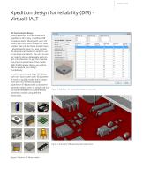
Xpedition design for reliability (DfR) Virtual HALT 3D Component Library Data preparation is streamlined with Xpedition’s 3D library. Xpedition DfR includes a starter library with over 4.8 million parts and 4000 unique 3D solid models. Not only do these models have a photorealistic view, but also contain the physical parameters in order to run an accurate simulation. You will no longer need to dig up datasheets and contact manufacturers to get the material and physical properties of the model. With the 3D starter library you will be able to analyze your design immediately. As well as...
Open the catalog to page 2
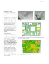
Preparing for Simulation With Xpedition DfR, meshing is optimized for the electrical domain, thus reducing setup time and making it easy to identify appropriate issues for your product. Boundary conditions can be pre-defined using jigs or mounting holes to ensure that the same environment is analyzed when the product is placed in the field. Users can create “what if” scenarios by defining an area they wish to place a boundary constraint, allowing users to identify and potentially resolve high deformation and reliability issues. Figure 5: Boundary conditions can be pre-defined using jigs...
Open the catalog to page 3
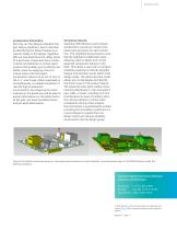
Acceleration Simulation Not only can the designer decipher the part failure prediction, due to vibration by identifying the failure frequency or natural modes in the design. Xpedition DfR can also determine the safety factor of a particular component due to stress. Constant Acceleration is a linear static analysis that enables you to identify reliability issues by applying a force to induce stress onto the board. Acceleration values can be set to any of the X, Y, and Z axes, either separately or simultaneously, to enable simulation of real-life high-acceleration environments. By analyzing...
Open the catalog to page 4All SIEMENS EDA catalogs and technical brochures
-
Calibre nmDRC
4 Pages
Archived catalogs
-
Tessent Connect
3 Pages
-
Calibre LFD
3 Pages
-
Vista Virtual Prototyping
4 Pages
-
Vista Architect
4 Pages
-
Tessent IJTAG
2 Pages
-
Calibre® MPCpro
2 Pages
-
LeonardoSpectrum
4 Pages
-
Oasys-RTL
3 Pages
-
Olympus-SoC
5 Pages
-
ICanalyst
4 Pages
-
Calibre RVE
3 Pages
-
Calibre nmLVS
3 Pages
-
Calibre LFD
3 Pages
-
Tanner L-Edit IC Layout
4 Pages
-
Tanner Designer
2 Pages
-
Tanner Waveform Viewer
2 Pages
-
Tanner T-Spice Simulation
2 Pages
-
ReqTracer
2 Pages
-
LeonardoSpectrum™
4 Pages
-
HDL Designer
2 Pages
-
Nucleus RTOS
2 Pages
-
Calibre ® MPCpro
2 Pages
-
Calibre OPC and PSM
6 Pages
-
Multicore Framework
2 Pages
-
Volcano VSTAR Ethernet
2 Pages
-
Volcano VSTAR AUTOSAR
2 Pages
-
CAT/TransCable
2 Pages
-
ReadyStart?
2 Pages
-
Inflexion UI
2 Pages
-
TransDesign
6 Pages
-
TransCable
2 Pages
-
TranSACT
2 Pages
-
TransOVM
2 Pages
-
TransBridge
2 Pages
-
Calibre xACT 3D
2 Pages
-
Volcano? VSA
2 Pages
-
Calibre xRC
3 Pages
-
Calibre xRC-CB
2 Pages
-
ces-ds
2 Pages
-
VolcanoBootloader
2 Pages
-
flovent
12 Pages
-
flotherm
8 Pages
-
floefd
12 Pages
-
Calibre DESIGNrev
2 Pages
-
Calibre xL
2 Pages
-
Calibre nmDRC
4 Pages
-
ADiT
2 Pages
-
Calibre RealTime
2 Pages
-
Questa ADMS
7 Pages
-
iSolve DigIQ Interface
2 Pages
-
Questa® Codelink Turbo
3 Pages
-
RC250
2 Pages
-
RC340
2 Pages
-
Atmel SAM9263
2 Pages
-
Sourcery Analyzer
2 Pages
-
Capital Migration Services
2 Pages
-
Capital Harness MPM
2 Pages
-
Vista
4 Pages
-
Capital ModularXC
2 Pages
-
Capital HarnessXC
2 Pages
-
Capital Integrator
2 Pages
-
Capital Logic
2 Pages
-
Volcano Bootloader
2 Pages
-
Calibre® OPCverify™
2 Pages
-
Nucleus
2 Pages
-
Mentor Embedded Linux
10 Pages
-
PADS AutoRouter
4 Pages
-
Board Station XE (BSXE
9 Pages
-
Board Architect
2 Pages
-
PADS Suites
3 Pages
-
AccuSim II
2 Pages
-
AccuParts™
1 Pages
-
FloVENT
12 Pages
-
FloTHERM PCB
2 Pages
-
FloTHERM® IC
2 Pages
-
Calibre OPCverify
2 Pages
-
Olympus-SoC
2 Pages
-
Catapult C Synthesis
4 Pages
-
NUCLEUS RTOS SOLUTIONS
2 Pages
-
EDGE Developer Suite
2 Pages
-
MAJIC JTAG Probe
3 Pages
-
Mentor Embedded Inflexion UI
2 Pages
-
CHS
4 Pages
-
VeSys
2 Pages
-
TransLayout™
2 Pages
-
PCB Systems Board Station XE
4 Pages
-
Mechanical Analysis FloEFD
7 Pages
-
Calibre nmOPC
2 Pages


