- Catalogs
- SIEB & MEYER AG
- Drive Controller SD2
Drive Controller SD2
1 /200Pages

Drive Controller SD2
1 /200Pages
Catalog excerpts
SIEB & MEYER Drive Controller SD2 Hardware Description Drive controller SD2, power supply unit PS2
Open the catalog to page 1
Copyright Original instructions, Copyright © 2025 SIEB & MEYER AG All rights reserved. This manual or extracts thereof may only be copied with the explicit authorization by SIEB & MEYER AG. Trademarks All product, font and company names mentioned in this manual may be trademarks or registered trademarks of their respective companies. SIEB & MEYER Worldwide For questions regarding our products and technical problems please contact us. SIEB & MEYER AG Auf dem Schmaarkamp 21 21339 Lueneburg Germany Phone: +49 4131 203 0 Fax: +49 4131 203 2000 [email protected] http://www.sieb-meyer.com SIEB & MEYER...
Open the catalog to page 2
6.3 Device Variant 0362111OF (max. 160 A) with Integrated Water-cooled Heat 6.4 Device Variant 0362111RF (max. 220 A) with Integrated Water-cooled Heat 6.5 Device Variant 0362111SF (max. 358 A) with Integrated Water-cooled Heat Drive Controller SD2 - Hardware Description
Open the catalog to page 3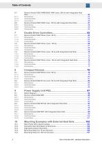
6.7 Device Variant 0362114MF/0362114NF (max. 200 A) with Integrated Heat Drive Controller SD2 - Hardware Description
Open the catalog to page 4
Drive Controller SD2 - Hardware Description
Open the catalog to page 5
Drive Controller SD2 - Hardware Description
Open the catalog to page 6
Drive Controller SD2 - Hardware Description
Open the catalog to page 7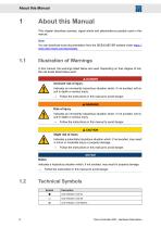
1 About this Manual This chapter descirbes symbols, signal words and abbreviations possibly used in this manual. You can download more documentation from the SIEB & MEYER website under https:// www.sieb-meyer.com/downloads. In this manual, the warnings listed below are used. Depending on their degree of risk, the risk levels listed below exist: A Imminent risk of injury Indicates an imminently hazardous situation which, if not avoided, will result in death or serious injury. ^ Follow the instructions in this manual to avoid danger. Indicates an imminently hazardous situation which, if not avoided,...
Open the catalog to page 8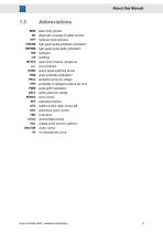
About this Manual basic drive module diagnostic coverage of safety function hardware fault tolerance high-speed pulse amplitude modulation high-speed pulse width modulation mean time to failure, dangerous not connected output signal switching device pulse amplitude modulation protective extra-low voltage probability of dangerous failure per hour pulse width modulation safety extra-low voltage servo control safe failure fraction safety function: Safe Torque Off sensorless vector control undervoltage-lockout voltage at the common collector vector control V/f characteristic curve Drive Controller...
Open the catalog to page 9
General Information This manual describes the drive controllers of the series SD2. Drive controllers of the generation SD2x are BDM (basic drive modules) that can be used either as frequency converter or as servo drive. These devices allow operation of high-dynamic servo motors as well as synchronous and asynchronous high-frequency spindles. The devices are equipped with interfaces for different sensor systems allowing to drive motors with resolvers as well as SinCos, EnDat, Hall, linear Hall, incremental and field plate sensors. Motor systems without any sensors are also supported, whereas different...
Open the catalog to page 10
Safety Instructions Safety Instructions These safety instructions include important information regarding your safety and must be observed during installation and operation of SIEB & MEYER devices. Read them carefully and keep them for later use. Also adhere to safety instructions in the product documentation and on the device. Standards and Regulations SIEB & MEYER devices comply with the regulations of the following standards and directives: ▶ Low-Voltage Directive 2014/35/EU: EU declaration of conformity, DIN EN 61800-5-1 ▶ EMC Directive 2014/30/EU: EU manufacturer's certificate, DIN EN 61800-3...
Open the catalog to page 11
Safety Instructions Working on the Device WARNING Trained staff → To avoid risks of serious injuries and material damage any works regarding installation, initial operation and maintenance must be carried out by trained staff only! Furthermore, electricians who connect feedin systems must be approved by the local DSO (distribution system operator). Trained staff, according to this fundamental safety instruction, are persons familiar with the installation, mounting, initial and permanent operation of the product and they are qualified appropriately for the work. The standards DIN VDE 0100 and...
Open the catalog to page 12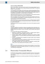
Safety Instructions Terms according to DIN EN 61800 Before initial operation, make sure that the machine will not expose danger (e.g. runaway moves). The conformity with the safety standards DIN EN 60204-1 and DIN EN 61800-5-1 must be ensured. The manufacturer of the system or the machine has to meet the requirements of the legal values regarding the electromagnetic compatibility (EMC). SIEB & MEYER products are designed for the operation in industrial areas provided that the supplied manual “Unit Assembly Complying EMC” has been taken into consideration. SIEB & MEYER tests all products in its...
Open the catalog to page 13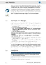
During design and construction of the machine as well as in the operation manual the machine manufacturer is obliged to give consideration to the intended (appropriate) use of the machine and risks arising from reasonably foreseeable misuse of the machine. To avoid injuries and material damage any use, installation and setup of SIEB & MEYER products by non-experts which exceed the technical data specified in the product documentation (high voltages, temperatures etc.) is considered to be not intended use and forbidden. Adhere to the safety instructions on the device and in the product documentation....
Open the catalog to page 14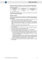
Mechanical installation conditions for the system according to DIN EN 61800-2: „Vibrations must remain within the limit values of the IEC 60721-3-3, class 3M2, standard for fixed equipment." Tab. 1: Vibration limits of the system "Vibrations which exceed these limits, or the use on mobile equipment, are considered as abnormal mechanical conditions." Operating conditions: The following requirements are to be considered for the installation and the operation of the device. Noncompliance with theses requirements is regarded as abnormal operating condition: ► The device is conceived according to...
Open the catalog to page 15All SIEB & MEYER AG catalogs and technical brochures
 Frequency Converter SD2B plus
48 Pages
 Unit Assembly Complying EMC
75 Pages
 drivemaster2
318 Pages
 050201
24 Pages
 CNC 8x.00
106 Pages
- Automation software solution
- Interface software
- Servo-amplifier
- Reporting software
- EDM software
- Machine software
- Frequency inverter
- Fieldbus servo-drive
- AC servo-amplifier
- Data management software
- Compact servo-amplifier
- EtherCAT servo-amplifier
- OPC software
- CNC
- Analog servo-amplifier
- Compact frequency inverter
- Asynchronous servo drive
- RS-232 servo drive
- Ethernet positioning controller
- IP20 frequency inverter