
- Catalogs
- Shenzhen Wanty Photoelectric Co., Ltd.
- TFT LCD display module WTY101A08A01LM


TFT LCD display module WTY101A08A01LM
1 /24Pages
TFT LCD display module WTY101A08A01LM
1 /24Pages
Catalog excerpts
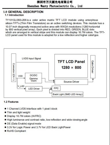
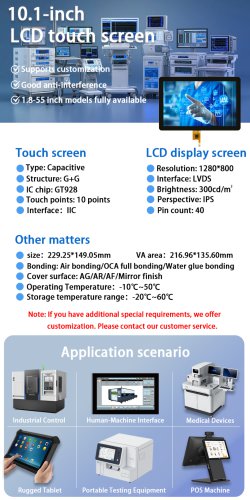
TY101GLI350-206 is a color active matrix TFT LCD module using amorphous silicon TFTs (Thin Film Transistors) as an active switching devices. This module has a 10.07 inch diagonally measured active area with WXGA resolutions (1280 horizontal by 800 vertical pixel array). Each pixel is divided into RED, GREEN, BLUE dots which are arranged in vertical stripe and this module can display 16.7M colors. The TFT-LCD panel used for this module is adapted for a low reflection and higher colortype. • 1 Channel LVDS Interface with 1 pixel /clock • High luminance and contrast ratio, low reflection and wide viewing angle • DE (Data Enable) signal mode • 3.3V for Logic Power and 3.7V for LED Back LightPower • RoHS Compliant
Open the catalog to page 1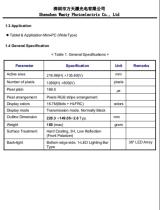
• Tablet & Application Mini-PC (WideType) < Table 1. General Specifications >
Open the catalog to page 2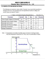
The followings are maximum values which, if exceed, may cause faulty operation or damage to the unit. The operational and non-operation a I maximum voltage and current values are listed in Table 2. < Table 2. LCD Module Electrical Specifications > fTa=25±2’Cl Note : 1) Temperature and relative humidity range are shown in the figure below. Wet bulb temperature should be 39 t;max. and no condensation of water.
Open the catalog to page 3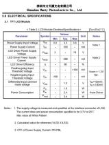
< Table 3. LCD Module ElectricalSpecifications > (Ta =25±2 C] Notes : 1. The supply voltage is measured and specified at the interface connector of LCM. The current draw and power consumption specified is for 3.7V at 25C Max value at White Pattern 2. Calculated value for reference (VLED XILED) 3. CTF of Power Supply Current: PD/PBL
Open the catalog to page 4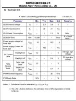
< Table 4. LED Driving guidelinespedfications > Ta=25+/-3°C Notes: 1. Calculator Value for reference Iled * Vled = Pleo 2. The LED Life-time define as the estimated time to 50% degradation of initial luminous.
Open the catalog to page 5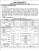
The lest of Optical specifications shall be measured in a dark room (ambient luminance 5 llux and temperature = 25±3t:) with the equipment of Luminance meter system (Goniometer system and TOPCON BM-7A) and test unit shall be located at an approximate distance 50cm from the LCD surface at a viewing angle of 0 and 4> equal to 0°. While scanning 9and/or 0. the center of the measuring spot on the Display surface shall stay fixed. The backlight should be operating for 30 minutes prior to measurement. VDD shall be 3.3+/- 0.3V at 25°C. Optimum viewing angle direction is 6 'clock. <Table 5. Optical Specifications>...
Open the catalog to page 6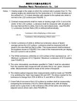
Notes : 1. Viewing angle is the angle at which the contrast ratio is greater than 10. The viewing angles are determined for the horizontal or 3,9 o'clock direction and the vertical or 6,12 o'clock direction with respect to the optical axis which is normal to the LCD surface (see FIGURE 1). 2. Contrast measurements shall be made at viewing angle of 0= 0 and at the center of the LCD surface. Luminance shall be measured with all pixels in the view field set first to white, then to the dark (black)state. (see FIGURE 1) Luminance Contrast Ratio (CR) is defined mathematically. Luminance when displaying...
Open the catalog to page 7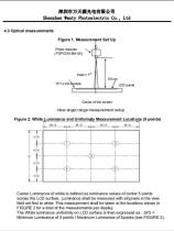
View angel range measurement setup Center Luminance of white is defined as luminance values of center 5 points across the LCD surface. Luminance shall be measured with all pixels in the view field set first to white. This measurement shall be taken at the locations shown in FIGURE 2 for a total of the measurements per display. The White luminance uniformity on LCD surface is then expressed as : AY5 = Minimum Luminance of 5 points / Maximum Luminance of 5points (see FIGURE 2).
Open the catalog to page 8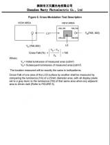
Ya - Initial luminance of measured area (cd/m2) Yb= Subsequent luminance of measured area (cd/m2) The location measured will be exactly the same in bothpatterns. Cross-Talk of one area of the LCD surface by another shall be measured by comparing the luminance (YA) of a 25mm diameter area, with all display pixels set to a gray level, to the luminance (YB) of that same area when any adjacent area is driven dark (Refer to FIGURE 5).
Open the catalog to page 9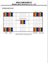
5.4 Data Input Format
Open the catalog to page 10
Shenzhen Wanty Photoelectric Co., Ltd
Open the catalog to page 12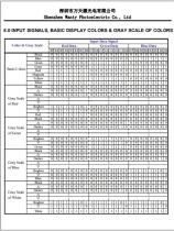
Shenzhen Wanty Photoelectric Co., Ltd 8.0 INPUT SIGNALS, BASIC DISPLAY COLORS & GRAY SCALE OF COLORS
Open the catalog to page 13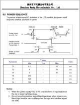
To prevent a latch-up or DC operation of the LCD module, the power otVoff sequence shall be as shown in below 1. When the power supply VDD is 0V, keep the level of input signals on the low or keep high impedance. 2. Do not keep the interface signal high impedance when power is on. Back Light must be turn on after power for logic and interface signal are valid.
Open the catalog to page 14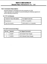
Physical interface is described as for the connector on LCM. These connectors are capable of accommodating the following signals and will be following components.
Open the catalog to page 15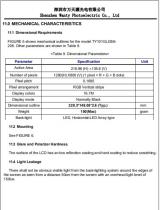
FIGURE 5 shows mechanical outlines lor the model TY101GLI350-206. Other parameters are shown in Table 9. <Table 9. Dimensional Parameters> 113 Glare and Polarizer Hardness. The surface of the LCD has an low reflection coating and hard coating to reduce scratching. There shall not be obvious visible light from the back-lighting system around the edges of the screen as seen from a distance 50cm from the screen with an overhead light level of 150lux.
Open the catalog to page 16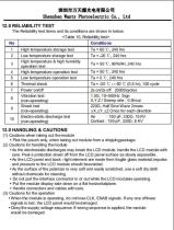
The Reliability test items and its conditions are shown in below. ____<Table 10. Reliability test>_ (1) Cautions when taking out the module • Pick the pouch only, when taking out module from a shipping package. (2) Cautions for handling the module • As the electrostatic discharges may break the LCD module, handle the LCD module with care. Peel a protection sheet off from the LCD panel surface as slowly aspossible. •As the LCD panel and back - light element are made from fragile glass material.impulse and pressure to the LCD module should beavoided. •As the surface of the polarizer is very soft...
Open the catalog to page 17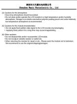
• Dew drop atmosphere should be avoided. • Do not store and/or operate the LCD module in a high temperature and/or humidity atmosphere. Storage in an electro-conductive polymer packing pouch and under relatively low temperature atmosphere is recommended. (5) Cautions for the module characteristics • Do not apply fixed pattern data signal to the LCD module at productaging. • Applying fixed pattern for a long time may cause imagesticking. •Do not disassemble and/or re-assemble LCD module. • Do not re-adjust variable resistor or switch etc •When returning the module for repair or etc.. Please pack...
Open the catalog to page 18All Shenzhen Wanty Photoelectric Co., Ltd. catalogs and technical brochures
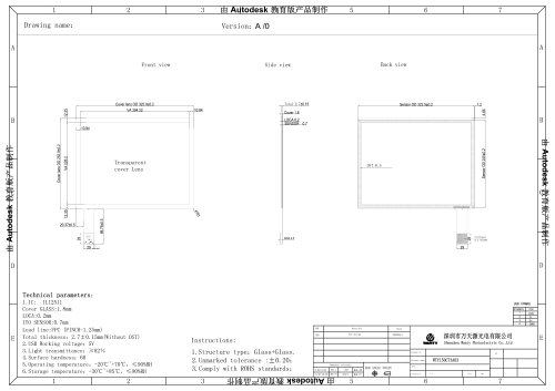
 WTY150C73A03
1 Page
 WTY133A41A02
1 Page
 触摸屏显示模块 WTY101225A07
1 Page
 WTY101225A02
1 Page
 WTY101565A08
1 Page
 LCD Touch Screen
1 Page
 WTY215599A01
1 Page
 WTY150C73A03
1 Page
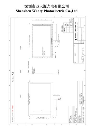 WTY156D24A01
1 Page
 T101GBP003-V0
19 Pages
 T070GBP001-V2
20 Pages
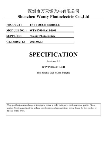 WTY070144A11-K01
19 Pages
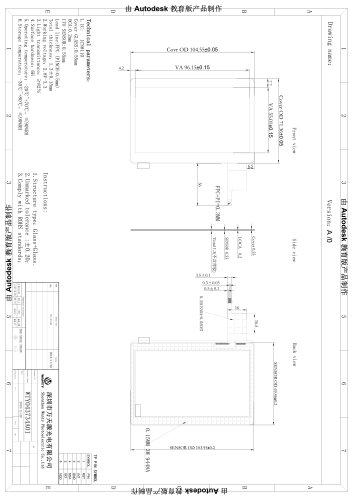 4.3 Inch Lcd Display
1 Page





- LCD display panel
- Industrial display panel
- TFT display module
- Color display panel
- Touch screen display panel
- IPS display panel
- Electronic display panel
- Backlit display panel
- LED-backlit display panel
- Medical equipment display
- Information display
- RGB display panel
- Outdoor display panel
- Instrumentation display panel
- Control panel display panel
- Built-in display
- Compact display panel
- Graphic display panel
- HDMI display panel