- Catalogs
- Shenzhen Sikes Electric Co., Ltd.
- SIKES SINEWAVE FILTERS
- Company
- Products
- Catalogs
- News & Trends
- Exhibitions
SIKES SINEWAVE FILTERS
1 /6Pages

SIKES SINEWAVE FILTERS
1 /6Pages
Catalog excerpts
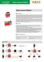
Sine wave Filters Sine wave Filters Descriptions Sikes Sine wave filters have been specially designed to improve the wave form and avoid overvoltages in the motors of VSD system. These low-pass filters are installed in inverters with PWM output, between the frequency inverter and the motor. Switching IGBT (isolated gate bipolar transistor) to high frequency causes an output voltage with peaks that can reach 1300 V (or more) in terminals and coils of the motor. These constant voltage values age the motor and decrease the performance of the coils, also wearing and pitting bearings, causing overheating and unnecessary noises and the transmission of interferences through cables. This effect becomes more obvious the greater the distance between the inverter and the motor. ■ Reduction of the overvoltage peaks caused by PWM and, therefore, a lower wear of motor insulation systems and bearings; ■ Reduction of motor noise and improves motor efficiency; ■ Improves the quality of the output wave of the PWM (pulse width modulator), reduces discharge currents driven by pulse frequency, especially in long lines connected to the motor. Recommended for up to 500m motor cable lengths with filter. ■ Attenuation of the interference emissions radiated by the conductors between the modulator and motor and improves the entire EMC load on the equipment. Technical Standards ■ Capacitors: CEI EN 60831-1/2, IEC 831-1/2 ■ Industrial network affected by harmonics: ■ Equipment: CEI EN 60439-1, IEC 439-1,ICE 60939 ■ Systems: EN 60439, EN 60831, EN 50081-1, EN 50081-2, clase A General Motor Protection / Variable Frequency Drive Step-up Transformer Medium Voltage Motor Long Motor Cable Leads AC Drive Motor Motor Motor Sinewavelter Motor Multip
Open the catalog to page 1
Features Main Characteristics Nominal system voltage (ph-ph) Operating frequency Switching freuquency Rated load power (P) Residual ripple voltage THD Standard voltage drop at rated current Maximum permanent overload 1,2 times rated current Maximum transient overload 2,0 times rated current Indoor standards Operating temperature Relative humidity Design features Block schematic Frequency Inverter Sine wave filter
Open the catalog to page 2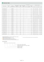
Selection Table Filter Model Motor drive rating @50Hz (kw) Connections Switching Weight frequency Copper (kg) Terminal (kHz) Bar ≥6 ≥6 ≥6 ≥5 Selection Recommendation: It's compulsory to collect all network conditions ■ Rated values and service type of the load to the filter ■ Rated values of other non-line loads ■ Indication of the point where the filter has to be installed ■ Presence and type of the power factor equipment in the network ■ Motor frequency, Switching frequency and fundamental operating frequency ■ For more technical details,plea
Open the catalog to page 3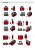
Mechanical data All dimensions in mm; 1 inch = 25,4 mm
Open the catalog to page 4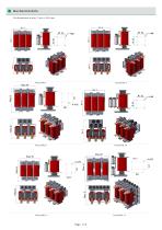
Mechanical data All dimensions in mm; 1 inch = 25,4 mm
Open the catalog to page 5
TERMINALS OR COPPER BAR Intput CIRCUIT WIRING Normally closed STANDARDS SIGNS TYPE Capacitors: CEI EN 60831-1/2, IEC 831-1/2 Industrial network affected by harmonics: CEI EN 61642 Equipment: CEI EN 60439-1, IEC 439-1,ICE 60939 Systems: EN 60439, EN 60831, EN 50081-1, EN 50081-2, clase A Observe protection clause to ISO 16016 请遵守ISO 16016的保密条款 DATE: 29.09.2020 Website: www.sikes-elec.com Email: sikes@s
Open the catalog to page 6All Shenzhen Sikes Electric Co., Ltd. catalogs and technical brochures
 Braking Unit Catalog-2025-04
5 Pages
 sikes LCL filter 11kw
4 Pages
 sikes harmonic filter 5.5kw THDI
3 Pages
 sikes harmonic filters
4 Pages
 Harmonic Filters
6 Pages
 EMC/EMI Filters
9 Pages
 Transformers
8 Pages
 Chokes
30 Pages
 Resistors
16 Pages
 Load bank
14 Pages
 Regenerative drive
22 Pages
 Sine wave filter
6 Pages


Archived catalogs
 Sine wave Filters
6 Pages
 Dynamic Braking Units
8 Pages
- Dry transformer
- Encapsulated transformer
- Electronic filter
- Power transformer
- Single-phase transformer
- Industrial transformer
- Isolation transformer
- Passive electronic filter
- Three-phase transformer
- AC electronic filter
- Low-pass electronic filter
- Protection transformer
- Cast resin transformer
- Transformer for industrial applications
- Wire-wound resistor
- 3-phase AC drive
- DIN rail mount transformer
- Toroidal transformer