- Catalogs
- SHENZHEN SENSOR ELECTRONIC TECHNOLOGY Co., LTD.
- Frequency Transducer
- Company
- Products
- Catalogs
- News & Trends
- Exhibitions
Frequency Transducer
1 /2Pages

Frequency Transducer
1 /2Pages
Catalog excerpts

Frequency Transducer www.ce-transducer.com Frequency Transducer Specifications: Operating Principle Photoelectric Isolation Isolation Voltage Response Time Power Consumption mW Mounting Vz, Vd, Iy Vg,Iz Output Output PCB/ 480 600 Din rail/ Screw Overload Capacity Part Numbers: Input Waveform R: Arbitrary wave pass zero CE-F01 3:0~5VDC (Vz) 2: 12V F: Square Wave. 4:0~20mA (Iz)* 3: 15V Z: Sine curve wave. 5:4~20mA (Iy)* 4: 24V O:OC frequency signal 8:0~10VDC(Vd) 8: 110V T: TTL electricity level 9:220V CE-F03 Z: Sine curve wave. Series Rated Input Case Accuracy Style (%) Frequency Voltage Power Supply S1 S3 * Loop resistance from 0 to 250Ω. Contact factory for loop resistance above 250Ω. Part Number Example: CE-F01-32FS3-0.5/0~55Hz (250V) Description: Frequency Transducer, Square Wave Signal (250V), Output: 0~5V, Power supply: +12V, Case Style: S3, Accuracy: 0.5, Input:0~55Hz. Connections Diagram (see page2 for mounting dimensions) Signal Input Signal Input Vout Power Supply Fig 1.1 CE-F01 Voltage Output, Case Style S Current Signal Output Power Supply Fig. 1.2 CE-F01 Current Output, Case Style S,
Open the catalog to page 1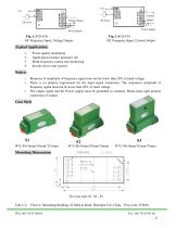
Vcc Vcc Current Voltage Output Power Supply Power Supply Fig. 1.3 CE-F01 OC Frequency Input, Voltage Output Fig. 1.4 CE-F01 OC Frequency Input, Current Output Power quality monitoring Applications monitor generator sets Multi-frequency control and monitoring Inverter drives and systems Response of amplitude of frequency signal must not be lower than 20% of rated voltage. There is no polarity requirement for the input signal connection. The responsive amplitude of frequency signal must not be lower than 20% of rated voltage. The output signal and the Power supply must be grounded in common. Please...
Open the catalog to page 2All SHENZHEN SENSOR ELECTRONIC TECHNOLOGY Co., LTD. catalogs and technical brochures
 Transducer with led display
13 Pages
 Digital Electrical Transducer
35 Pages
 Analog Electrical Transducer.
84 Pages
 Current Transducer
8 Pages
 Voltage Transducer
8 Pages
 Signal Isolator
3 Pages
 Self-powered Transducer
6 Pages
 Power transducer
3 Pages
 Power Factor Transducer
3 Pages
 AC voltage transducer
6 Pages
 AC current transducer
6 Pages
 DC voltage transducer
3 Pages
 DC current transducer
4 Pages
 3 phase power tranducer
3 Pages
 1 phase Power transducer
2 Pages
 DIGITAL TRANSDUCER Series CE?A
35 Pages


Archived catalogs

- Display module
- Transformer
- Measuring device
- Switching relay
- LED display panel
- Current transformer
- Single-phase transformer
- Current sensor
- AC current sensor
- DC current sensor
- Solid state relay
- Current transducer
- RS-485 display panel
- Signal converter
- Hall effect current sensor
- Electronic gauge
- DC solid state relay
- AC current transducer
- DC current transducer
- Presence detector