- Catalogs
- SHENZHEN SENSOR ELECTRONIC TECHNOLOGY Co., LTD.
- Analog Electrical Transducer.
- Company
- Products
- Catalogs
- News & Trends
- Exhibitions
Analog Electrical Transducer.
1 /84Pages

Analog Electrical Transducer.
1 /84Pages
Catalog excerpts
ELECTRICAL TRANSDUCER CE-T Series
Open the catalog to page 1
Introduction Shenzhen Sensor Electronic Technology Co., Ltd specializes in researching, developing and manufacturing of electrical transducers. Our advanced test instrumentation and engineering capabilities provide a most favorable environment for transducer manufacturing. Our quality and inspection departments are among the most advanced in China. The output of our production facility is over one hundred thousand units annually. The most important aspect of our production is “Quality”. Our products are manufactured and certified to the 2000 quality standards of ISO 9001. The transducers have...
Open the catalog to page 2
Chapter 1 Selection Guide Chapter 2 Product Overview Chapter 3 Details of the Electrical Transducer Chapter 4 Case style and Mounting Diagram Chapter 5 Notes for Ordering
Open the catalog to page 3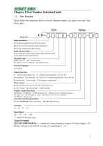
SxTMMK Chapter 1 Part Number Selection Guide 1.1 Part Number Please follow the instruction below to fix the full part number, one square one code, from left to right. Series Series CE Input parameter -I: current V: voltage F: frequency P: active power Q: inactive power G: current & voltage combination W: location (potentiometer); R: resistance Input characteristics ■ J: AC; Z: DC; H: AC/DC; M: pulsating DC; B: bi-directional DC (Leave blank for power and frequency) Function codes 01-09: 1-element 22: 2-element/2 Way; 31: 3-phase 3-wire or 3-element 41: 3-phase 4-wire Output functions 1: tracking...
Open the catalog to page 4
1.2 Main Series List MAIN SERIES LIST FOR CE-T ANALOG ELECTRICAL PARAMETER TRANSDUCER FUNCTION TYPE Frequency Split Core Self Power Current Self Power Voltage Power supply
Open the catalog to page 5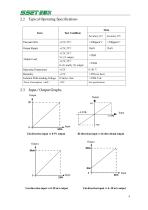
Bi-direction input vs bi-directional output Uni-direction input vs 0-20 mA output Uni-direction input vs 4~20 mA output
Open the catalog to page 7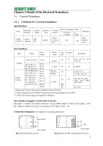
SSMTMttR Chapter 3 Details of the Electrical Transducer 3.1 Current Transducer 3.1.1 1-element AC Current Transducer Part Numbers: Series * Output types Vg,Vy,Vd,Id are not available in series CE-IJ03A. ** Loop resistance from 0 to 250Q. Contact factory for loop resistance above 250 Q *** Select 24 V Power supply for output of 4~20mA Id; Part Number Example: CE-IJ03-54ES3-O.5/0~50A Description: 1-element AC Current Transducer, average RMS, Output: 4~20mA, Power supply: +24V DC, Aperture: 020mm, Case style: S3, Accuracy: 0.5%, Input: 0~50A AC. Connections Diagrams (See Chapter4 for mounting dimensions)...
Open the catalog to page 8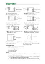
Signal Tnniit Voltage Signal Output Signal Tnput Power Supply Fig. 3.13 for CE-TJ03, CE-TJ03A Terminal Input, Voltage Output, Case-S Voltage Signal output Power Supply -o Current Signal Output Power Supply Fig. 3.1.4 for CE-TJ03, CE-TJ03A Terminal Tnput, Current Output, Case-S, Fig. 3.1.9 for CE-TJ03 , Power supply 220/110V Fig. 3.1.10 for CE-TJ03, Case style LH7 Window Tnput, Case style SK Red (black) wire: Positive (negative) power supply Yellow wire: Signal output 1. Multi-point current sensing and control panels 2. Monitor lighting elements 3. Monitor heating elements 4. Remote current...
Open the catalog to page 9
*Tracking output (Vg,Iz,Vd) type not available in series CE-IJ31A ** Loop resistance from 0 to 250Q. Contact factory for loop resistance above 250 Q ***When select MSK case style, the input should be =S5A Part Number Example: CE-IJ31-32BS3-0.5/0~5A Description: 3 elements AC Current Transducer, average RMS, Output: 0-5Vdc, Power supply: +12Vdc, Aperture: ®6.5mm, Case style: S3, Accuracy: 0.5 %, Input: 0-5A AC. Connections Diagram (See Chapter4 for mounting dimensions)
Open the catalog to page 10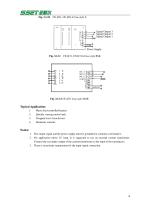
Signal Output 3 Signal Output 2 Signal Output 1 =-ooo Q Power Supply Fig. 3.1.11 CE-IJ31, CE-IJ31A Case style BSK Typical Application: 1. Phase fired controlled heaters 2. Quickly varying motor loads 3. Chopped wave form drivers 1. The output signal and the power supply must be grounded in common at terminal 6. 2. For application above 25 Amp, It is suggested to use an external current transformer. Connect the secondary output of the current transformer to the input of the transducers. 3. There is no polarity requirement for the input signal connection.
Open the catalog to page 11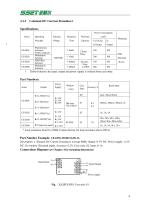
Signal Output Power supply
Open the catalog to page 12
Signal Input Hi -o Voltage Signal Output Signal Input Current Signal Output Fig. 3.1.14CE-IZ02 Power supply Voltage Output, Case style S Power supply Fig. 3.1.19 CE-IZ04, CE-IZ06 Frequency Output, Case style S Fig. 3.1.20 CE-IZ02 Voltage Output, Case style H2 Fig. 3.1.21 ce-IZ02 Current Output, Case style H2 Typical Applications: 1. Power supply management 3. Battery chargers and systems 1. If the input signal is bi-directional DC or pulse DC, please indicate in your order. 2. In case a current (>1A) is input through the terminals, it is advisable to connect terminals 1&2 in parallel, and terminals...
Open the catalog to page 13
* Output types (Vg,Vy,Vd,) and accuracy 0.2 are not available in series CE-IJ03A. ** Loop resistance from 0 to 250Q. Contact factory for loop resistance above 250 Q *** Select 24 V Power supply for output of 4~20mA Id; Output type Id is not available in series CE-VJ03A. **** H1 case style needs an extra voltage divider Part Number Example: CE-VJ03-52MS2-0.5/0~250V Description: 1-pahse AC Voltage Transducer, Output: 4~20mA, Power supply: +12V, Without Window (terminal input), Accuracy: 0.5, Case style: S2 Input: 0-250V.
Open the catalog to page 14
Connections Diagram (see Chapter 4 for mounting dimensions) Current Limiting Signal Input Voltage Output Signal Output Signal Input Power Supply Power Supply Signal Input Fig. 3.2.2 CE-VJ03, CE-VJ03A Voltage Output, Case style S Signal Input Signal Output Power Supply Fig. 3.2.3 CE-VJ03, CE-VJ03A Current Output, Case style S Power Supply Fig. 3.2.4 CE-VJ03 Loop power, Case style S Monitor for over/under voltage Power monitoring Multi-point instrumentation needs Sense phase loss Selection of output signal: Please select Power supply >15V when you need 0~10V output. The H1 type must be used with...
Open the catalog to page 15
Part Numbers: Series * Tracking output (Vg, Iz, Vd) type not available in CE-VJ31A, CE-VJ41A and now the accuracy only 0.5. ** Loop resistance from 0 to 250Q. Contact factory for loop resistance above 250Q. Part Number Example: CE-VJ41-32MS3-0.5/0~250V Description: 3-phase 4-wire AC Voltage Transducer, Output: 0-5V, Power supply:+12V, no Window, Case style S3 , Accuracy: 0.5, Input: 0-250V. Connections Diagram (see Chapter 4 for mounting dimensions) Phase-A Phase-B Phase-C Signal Signal Power Supply
Open the catalog to page 16All SHENZHEN SENSOR ELECTRONIC TECHNOLOGY Co., LTD. catalogs and technical brochures
 Transducer with led display
13 Pages
 Digital Electrical Transducer
35 Pages
 Current Transducer
8 Pages
 Voltage Transducer
8 Pages
 Signal Isolator
3 Pages
 Self-powered Transducer
6 Pages
 Power transducer
3 Pages
 Power Factor Transducer
3 Pages
 AC voltage transducer
6 Pages
 AC current transducer
6 Pages
 Frequency Transducer
2 Pages
 DC voltage transducer
3 Pages
 DC current transducer
4 Pages
 3 phase power tranducer
3 Pages
 1 phase Power transducer
2 Pages
 DIGITAL TRANSDUCER Series CE?A
35 Pages


