- Catalogs
- SHENZHEN SENSOR ELECTRONIC TECHNOLOGY Co., LTD.
- 3 phase cross function transducer
- Company
- Products
- Catalogs
- News & Trends
- Exhibitions
3 phase cross function transducer
1 /9Pages

3 phase cross function transducer
1 /9Pages
Catalog excerpts
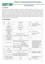
3-Phase Cross-functional Electrical Transducer www.ce-transducer.com A. Overview The transducer has multifunction including electric parameters acquisition, detecting switching value, control and transducing. It can measure almost all parameters of 3-phase 4-wire circuit including voltage, current, frequency, active power, reactive power, power factor, accumulated energy consumption and switching value. It adopts all-digital sampling technology and features high accuracy, good stability and high communication speed. Its complete electric isolation design makes strong noise-proof ability. It accepts current, voltage and/or switching value input and has some optional outputs including standard RS-485/RS232 digital port, relay and/or pulse switching value output. These outputs ensure the transducer can be easily connected to computer system and network. Also it can output an analog value and you can select any one of parameters to be the analog output. Baud rate Voltage/Current: 0.2 8 data bits, no checksum, one stop bit. Communication Interface Output protocol Maximum number of communication nodes Bus protection capability Analog output load Interval of interior data acquisition Operating temperature range -10℃ ~ +55℃ Between input and output: 2500V DC/1min. Between input and power supply: 2500V DC/1min. Between output bus and power supply: 2500V DC/1 min. 2 times of the maximum value of measuring voltage, 1 minute duration, 10 seconds interval, 10 times repeat; Isolation voltage Overload capability Power supply Power consumption Relay / pulse output Contact current-carrying rating: 3A/250V AC, Open collector output load capacity: 40 mA Pulse width of switching value output: 1 sec. Maximum measured accumulated energy Temperature drift Here: Input means AC input. Output means analog output. Ground of switching value input, analog output and power supply are in common. When input oversteps measure range, the accuracy will be deteriorative. Different power consumption for different power supply. For maximum input value of measuring range. ppm/℃
Open the catalog to page 1
Analog Input —— 3-phase AC current, voltage, frequency. Switching value input —— 4 switching value inputs, dry contacts, potential: +12V or +24V. Output data —— True RMS of voltage Ua, Ub, Uc and current Ia, Ib, Ic; frequency F; bi-direction active power P; bi-direction reactive power Q; bi-direction power factor COSΦ, bi-direction active energy, bi-direction reactive energy (memory with power failure protection function) and switching value output. Measuring range —— Voltage: 100V, 220V, 380V, 500V optional. Current: 1A, 5A optional. Relay / pulse output —— 2 switching value outputs (relay or...
Open the catalog to page 2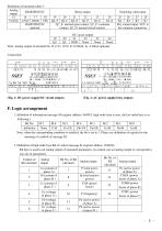
Definition of terminals table 2: Analog RS485/RS232C output 15 16 17 18 Vz/Iz/Iy A/TXD B/RXD VSS RS485 RS232C optional Relay output Switching value input 25 26 27 28 K4 K3 K2 K1 Dry contact input, VCC is for common connection. OC circuit output 19 20 21 22 23 24 Q2 Q1 GND None None None Note: Analog output of terminal No.15 is Vz: 0-5V, Iz :0-20mA, Iy: 4-20mA optional. Connection: (Fig. 1: DC power supply/OC circuit output) (Fig. 2: AC power supply/relay output) F. Logic arrangement 1. definition of information message M (register address: 0x0015, high order byte is zero, the low order byte is...
Open the catalog to page 3
3. Definition of low order byte Kl of control message K (register address: 0x0016): 3.1 Q1 output logic arrangement 3.1.1 If((M.0|M.1|M.2)&&(Kl==1)) Q1 will output a pulse with width of 1 second or make contacts of relay output closed for 1 second. Note: when the value of Ia or Ib or Ic is greater than that of Ik register and the value of control register Kl is 1, Q1 output will happen. 3.1.2 If((M.3|M.4)&&(Kl==2)) Q1 will output a pulse with width of 1 second or make contacts of relay output closed for 1 second. Note: when the value of Ua or Ub or Uc is less than that of Uk register and the...
Open the catalog to page 4
H. MODBUS protocol 1. Format of message (1). Function code 0x03 —— inquiry the content of register of slave equipment. The message from master equipment: Address of the slave equipment 0x01-0xFF 1 byte Function code Address of the first register Quantity of Registers CRC code The correct response message from the slave equipmen: Address of the slave equipment 0x01-0xFF 1 byte Function code 0x03 1 byte Number of data bytes 2 x N* 1 byte Data section (contents of registers) N* x 2 Bytes CRC code 2 bytes *N = Quantity of Registers (2). Function code 0x06 ── To set (write) data of single register...
Open the catalog to page 5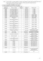
Note: 1. For all Address of register, Quantity of registers and Contents of register (Data), their high order byte is before their low order byte. But the low order byte of CRC code is before the high order byte. 2. The length of the register is 16 bits (2 bytes). 2. Format of commands and definition of the registers (1). List of definition of registers of electrical parameters data Address of Quantity of Attribute of Content of register Range of data register (Hex) registers register 0x0000 Ia (current of phase A) 1 Read only 0~12000 0x0001 Ib (current of phase B) 1 Read only 0~12000 0x0002...
Open the catalog to page 6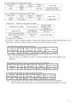
(2). List of definition of transducer name register: register address content of number of (Hex) register registers transducer 0x0021 2 name Read only arranged according to tranducer’s kind. (4 bytes) (3). List of definition of switching value and OC output: register address content of number of Attribute of register registers register (Hex) 0x0028 Pulse output 1 write range of data as attached list A Attached list A: definition of data (content) of register Q2 (electrical level output) high order byte Q1 (pulse output, controlled by master equipment.)) 4 low order bits of low order byte 4 high...
Open the catalog to page 7
3. Data List of the format of data responded after a read command (suppose the rated value of voltage is 100V, the rated value of current is 5A): Parameter Decimal Data Hex. data (100%) Value No. data (100%) High byte Low byte 1 IA 5A 27 10 10000 True RMS 2 IB 5A 27 10 10000 True RMS 3 IC 5A 27 10 10000 True RMS 4 UA 100V 27 10 10000 True RMS 5 UB 100V 27 10 10000 True RMS 6 UC 100V 27 10 10000 True RMS Total active 7 P 1500W 27 10 10000 power Total reactive 8 Q 1500Var 27 10 10000 power Total power 9 COS 1.0000 27 10 10000 factor 10 F 50Hz C3 50 50000 frequency active power of 11 Pa 500W 27...
Open the catalog to page 8All SHENZHEN SENSOR ELECTRONIC TECHNOLOGY Co., LTD. catalogs and technical brochures
 Transducer with led display
13 Pages
 Digital Electrical Transducer
35 Pages
 Analog Electrical Transducer.
84 Pages
 Current Transducer
8 Pages
 Voltage Transducer
8 Pages
 Signal Isolator
3 Pages
 Self-powered Transducer
6 Pages
 Power transducer
3 Pages
 Power Factor Transducer
3 Pages
 AC voltage transducer
6 Pages
 AC current transducer
6 Pages
 Frequency Transducer
2 Pages
 DC voltage transducer
3 Pages
 DC current transducer
4 Pages
 3 phase power tranducer
3 Pages
 1 phase Power transducer
2 Pages
 DIGITAL TRANSDUCER Series CE?A
35 Pages


Archived catalogs

- Display module
- Transformer
- Measuring device
- Switching relay
- LED display panel
- Current transformer
- Single-phase transformer
- Current sensor
- AC current sensor
- DC current sensor
- Solid state relay
- Current transducer
- RS-485 display panel
- Signal converter
- Hall effect current sensor
- Electronic gauge
- DC solid state relay
- AC current transducer
- DC current transducer
- Presence detector