
- Catalogs
- SHENZHEN SENSOR ELECTRONIC TECHNOLOGY Co., LTD.
- 1 phase Power transducer

- Company
- Products
- Catalogs
- News & Trends
- Exhibitions
1 phase Power transducer

1 phase Power transducer
The 1-Phase Power Transducer operates on an electromagnetic isolation principle with a voltage isolation of 2500V DC and a response time of ≤700ms. It has an overload capacity of 20 times for current and 2 times for voltage. Power consumption is 600mW for CE-P02 and 750mW for CE-Q02. Mounting options include screw or DIN rail.
Part Numbers and Configurations
The transducer is available in different configurations based on rated input, series output, power supply, window size, and case style. Accuracy is 0.5%, with voltage options ranging from 75V to 500V and current options from 5A to 25A. Output options include 0~5V DC, 0~20mA, and 4~20mA.
Applications
Typical applications include motor efficiency monitoring, multi-point power sensing, energy management, and remote power sensing over long distances.
Installation and Usage Notes
The input current must pass through the window in the specified direction. For currents larger than 25A, an AC current mutual inductor (CT) is recommended. The output signal for a 3-phase power transducer corresponds to the total power of the three phases.
Case Styles and Dimensions
The transducer is available in case styles S3 and SK, with dimensions provided for mounting. The S3 case style measures 36mm x 83mm x 76mm, while the SK style measures 63mm x 108mm x 84mm.
Contact Information
The manufacturer is located at Floor 4, Shenzheng Building, 42 MeiLin Road, Shenzhen City, China. Contact details include phone: +86-755 83766915 and fax: +86-755 83763161.
Catalog excerpts
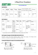
1-Phase Power Transducer www.ce-transducer.com Specifications Series Operating Principle Electromagnetic Isolation Isolation Voltage Response Time Overload Capacity Power ConsumptionmW Vz,Vd,Vg,Iz Output Iy Output Part Number Example: CE-P02-52BS3-0.5/0~250V*0~5A Description: 1-phase Active Power Transducer, Output: 4~20mA, Power Supply: +12V, Window: Ф6.5, Accuracy: 0.5, Case Style: S3, Input Voltage: 0~250V, Current: 0~5A, Connections Diagram (see page 2 for mounting dimensions) Voltage Signal Voltage Signal Vout Current Signal Output Power Supply Power Supply Fig. 1.1 CE-P02, CE-Q02 Voltage Output, Case Style S Fig. 1.2 CE-P02, CE-Q02 Current Output, Case Style S
Open the catalog to page 1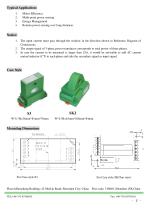
Motor Efficiency Multi-point power sensing Energy Management Remote power sensing over long distances Notice: 1. The input current must pass through the window in the direction shown in Reference Diagram of Connections. 2. The output signal of 3-phase power transducer corresponds to total power of three phases. 3. In case the current to be measured is larger than 25A, it would be advisable to add AC current mutual inductor (CT) to each phase and take the secondary signal as input signal. Case Style Center of the sliding track For Case style SK(Top view) Floor4;Shenzheng Building; 42 MeiLin Road;...
Open the catalog to page 2All SHENZHEN SENSOR ELECTRONIC TECHNOLOGY Co., LTD. catalogs and technical brochures
 Transducer with led display
13 Pages
 Digital Electrical Transducer
35 Pages
 Analog Electrical Transducer.
84 Pages
 Current Transducer
8 Pages
 Voltage Transducer
8 Pages
 Signal Isolator
3 Pages
 Self-powered Transducer
6 Pages
 Power transducer
3 Pages
 Power Factor Transducer
3 Pages
 AC voltage transducer
6 Pages
 AC current transducer
6 Pages
 Frequency Transducer
2 Pages
 DC voltage transducer
3 Pages
 DC current transducer
4 Pages
 3 phase power tranducer
3 Pages
 DIGITAL TRANSDUCER Series CE?A
35 Pages


Archived catalogs

- Display module
- Transformer
- Measuring device
- Switching relay
- LED display panel
- Current transformer
- Single-phase transformer
- Current sensor
- AC current sensor
- Solid state relay
- DC current sensor
- Current transducer
- RS-485 display panel
- Signal converter
- Hall effect current sensor
- AC current transducer
- DC solid state relay
- Electronic gauge
- DC current transducer
- Energy meter transformer