
- Catalogs
- Shenzhen Ruicom Technology Co., Ltd.
- WDS826FL Special dual axis tilt angle sensor for wind turbine tower shaking

WDS826FL Special dual axis tilt angle sensor for wind turbine tower shaking

WDS826FL Special dual axis tilt angle sensor for wind turbine tower shaking
The WDS826FL is a dual-axis tilt angle sensor designed for monitoring wind turbine tower shaking. It features excellent low-frequency response, full temperature range calibration, and long-term stability testing. The sensor supports MODBUS protocol and offers RS485, RS422, and RS232 output interfaces. It is easy to install and resistant to electromagnetic interference and vibration.
This sensor is suitable for wind power monitoring, bridge and dam monitoring, ancient building monitoring, high-speed rail track monitoring, and more.
- Dual axis inclination measurement
- Range: ±10°
- Resolution: 0.0005°
- Output options: RS485 / RS422 / RS232
- Measure range: ±10°
- Measure accuracy: 0.05° at room temperature
- Power supply: 9-36V
- Working temperature: -40 to +85°C
- Protection grade: IP67
- Power supply: 9-36V
- Working current: 33mA at 12V, 19mA at 24V
- Working temperature: -40 to +85°C
The red indicator light remains on when powered and flashes during communication.
Detailed pin color definitions for RS232, RS485, and RS422 connections are provided.
Shell size: L82 × W70 × H42mm
Installation size: L71 × W56 × H8mm
The sensor supports Serial Communication Protocol and MODBUS RTU. Default settings include a baud rate of 9600, no parity, and 1 stop bit. Various commands are available for reading angles, setting zero points, and configuring output modes.
Uses RTU mode with CRC16 check data. Supports reading and writing registers with specific data types like INT16 and UINT32.
This document provides technical specifications and operational procedures for a specific model of tilt sensors used in bus systems. It includes instructions for setting up, testing, and configuring the sensors, as well as details on communication protocols and data interpretation.
- Commands must be sent twice consecutively to ensure reliability. The host must not insert other data frames between queries and responses.
- Each power-on allows for one parameter change, indicated by a communication indicator flashing once per second.
- Users can access different axis data by adjusting register addresses and lengths. Key registers include:
- X-axis angle (Register 40003)
- Y-axis angle (Register 40005)
- Temperature data (Register 40007)
- Product address (Register 40018)
- Serial port baud rate (Register 40019)
- MODBUS function code 03H is used to read data. The data fields in the slave reply frame are parsed to obtain X and Y-axis angles and temperature.
- Angle conversion involves obtaining the current angle point count, converting to decimal, subtracting an offset, and multiplying by a coefficient.
- Relative/Absolute Zero: Use MODBUS function code 06H. Commands must be sent twice for effectiveness.
- Sensor Address: Default is 1. Use function code 06H to change, requiring two consecutive commands.
- Serial Port Baud Rate: Factory default is 9600bps. Use function code 06H to set, with options ranging from 4800 to 115200bps.
- Parity Bit: Factory default is even parity. Options include no parity and odd parity.
- Output Mode: Factory default is 0Hz. Options include Q&A mode and frequencies from 5Hz to 100Hz.
- Latitude: Default is 22.69°. Set using function code 06H, with a coefficient of 0.01.
- Filter Length: Controls the sensor's filter length, requiring a power cycle to take effect.
- Examples are provided for setting relative/absolute zero, sensor address, baud rate, parity check, output mode, latitude, and filter length.
For further assistance, contact Ruicom Technology via their website, phone, or email.
Catalog excerpts

WDS826FL Special dual axis tilt angle sensor for Product manual wind turbine tower shaking V1.1-20260708
Open the catalog to page 1
Technical Characteristics ❖ Dual axis inclination measurement; ❖ Good low-frequency characteristics; ❖ Output options: RS485 / RS422 / RS232 (optional). WDS826FL is a dynamic tilt measurement product designed specifically for monitoring the shaking of wind turbine towers. It has excellent low-frequency response characteristics and can effectively capture slowly changing tilt signals, meeting the precise measurement needs in low-frequency dynamic scenarios. Before leaving the factory, the products undergo full temperature range calibration compensation and long-term stability testing to ensure...
Open the catalog to page 2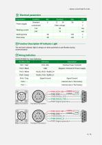
Electrical parameters
Open the catalog to page 4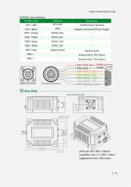
- www.ruicomtech.com RS422Pin Color Definition Pin/Wire Color Positive Power Terminal Negative Terminal Of Power Supply Signal Ground Signal Ground Size Chart Shell size: L82 × W70 × H42mm Installation size: L71 × W56 × H8mm Suggested screws: 4 M6 screws
Open the catalog to page 5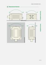
Measurement Direction Horizontal installation Vertical installation
Open the catalog to page 6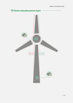
Vibration Swing Measurement Legend
Open the catalog to page 7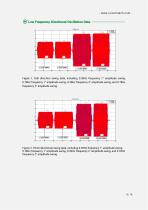
Low Frequency Directional Oscillation Data PDA826FL Roll 2.5 Figure 1. Roll direction swing data, including 0.39Hz frequency 1° amplitude swing, 0.78Hz frequency 1° amplitude swing, 0.39Hz frequency 2° amplitude swing, and 0.78Hz frequency 2° amplitude swing. Figure 2. Pinch directional swing data, including 0.39Hz frequency 1° amplitude swing,
Open the catalog to page 8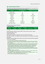
The product includes Serial Communication Protocol and MODBUS RTU two protocols. The default configuration parameters of the protocol are as follows:_ Serial Communication Protocol1. Data frame format: Identifier Default parameters: address 0, baud rate 9600,1 start bit, 8 data, no parity, 1 stop bit. Valid setting address: 0~254 Identifier: fixed as 0x68; Data length: the length from data length to checksum (including checksum); Data field: according to the different content and length of the command word changes accordingly; Checksum: The sum of data length, address code, command word and data...
Open the catalog to page 9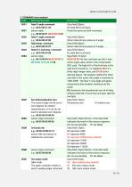
2. COMMAND word analysis
Open the catalog to page 10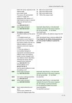
03 25Hz Auto output mode 04 35Hz Auto output mode 05 50Hz Auto output mode 06 100Hz Auto output mode before the sensor responds to the relative angle. Auto output mode: The sensor will automatically output X, Y angle and temperature after power on. If high frequency output is required, please set the baud rate to 115200. e.g.: 68 05 00 0C00 11 sensor reply command Data field (1byte)The No. in the data field e.g.: 68 05 00 8C 00 91 indicates the result of the sensor response 00: set successfully FF: set failed Set address command Data field(1byte) Note: All products have a common address: FF,...
Open the catalog to page 11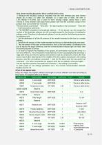
Note, please read the description below carefully before using: 1> Because the MODBUS protocol stipulates that the time between two data frames should be at least 3.5 bytes (for example, at a baud rate of 9600, the time is 3.5x(1/9600)x11=0.004s). But in order to leave enough margin, please leave a time interval of 10ms between each data frame, please note that the automatic output of the product does not consider the T3.5 time. The host sends a command -- 10ms idle -- the slave replies to the command -- 10ms idle -- the host sends a command... 2> The MODBUS stipulates the broadcast address----0,...
Open the catalog to page 13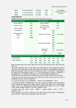
Note: The data fields of the slave reply frame are 50H, 46H, 00H, 00H, 23H, 20H, 00H, 00H, 03H, 57H The X-axis represents the 1st to 4th bytes of the data field, the Y-axis represents the 5th to 8th bytes of the data field, and the lower bytes come first.The representation method of angle is dot notation, where one point corresponds to 0.0001 °, and 0.0001 x (dot offset) is the angle.If the measurement range is ± 10 °, the total number of points is 200000.So 0 corresponds to -10 °, 200000 corresponds to+10 °, and 100000 corresponds to 0 °. Taking the above data frame as an example: the process...
Open the catalog to page 14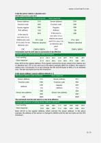
5.Set the sensor relative / absolute zero: MODBUS function code 06H Note: 0011H is the register address, which controls the sensor address. In the above example, the address of the sensor is changed to 0004H, and the last two bytes are the CRC checksum.
Open the catalog to page 15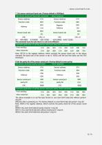
7. Set sensor serial port baud rate: (Factory default is 9600bps) The above example is to set the byte format to: one start bit+8 data bits without parity+1 stop bit Effective after re powering on. The factory default is a start bit+8 data bit parity+1 stop bit Note: 0009 is the register address, which controls the parity check bit of the sensor serial port. 0000H: One start bit+8 data bit parity checks+1 stop bit 0001 H: One start bit+8 data bits without checksum+1 stop bit 0002H: One start bit+8 data bits odd parity+1 stop bit
Open the catalog to page 16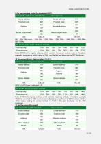
9.Set sensor output mode: (factory default 0HZ)
Open the catalog to page 17
Note: 000EH is the register address, which controls the filter length of the sensor. In the above example, the sensor filter length is set to 32, and the last two bytes are the CRC checksum. Note: After setting the filtering length, it needs to be powered on again to take effect. Web:www.ruicomtech.com Tel:0755-23087719 E-mail:[email protected] Add:Building 1, Lixin Lake Creative Park, 1 Furui Rd, Fuhai St, Bao'an, Shenzhen, China
Open the catalog to page 18All Shenzhen Ruicom Technology Co., Ltd. catalogs and technical brochures
 STSL Low-Power Tilt Sensor
21 Pages
 STS STANDARD OUTPUT TILT SENSOR
13 Pages
 HTS3D High-Precision Tilt Sensor
15 Pages
 GDS8 Series Digital inclinometer
13 Pages


















- Display module
- Industrial display panel
- Color display panel
- Tilt sensor
- Digital inclination sensor
- Built-in display
- 2-axis tilt sensor
- MEMS inclination sensor
- Multi-axis tilt sensor
- Analog inclination sensor
- RS-485 display panel
- High-precision tiltmeter
- IP67 inclination sensor
- 1-axis tilt sensor
- Vibration sensor
- Rugged inclination sensor
- High-resolution inclinometer
- 2" display
- Angle measurement inclination sensor
- RS-485 inclinometer