
- Catalogs
- Shenzhen Ruicom Technology Co., Ltd.
- VTS6D Vibration Tilt Angle Sensor

VTS6D Vibration Tilt Angle Sensor

VTS6D Vibration Tilt Angle Sensor
The VTS6D is an industrial-grade sensor designed for precise vibration and tilt angle measurement. It features full-temperature-range calibration and stability testing, ensuring reliable performance across various environments. The sensor employs an FFT algorithm to detect mechanical vibrations within the 0.5~20Hz range, allowing for accurate calculation of peak velocity and displacement amplitude. It supports multiple communication protocols, including MODBUS, and offers interface options like RS485/RS422/RS232. The non-contact installation design enhances deployment efficiency, and the sensor is resistant to electromagnetic interference and mechanical shock.
- Dual axis inclination measurement
- Range: ±10°
- Accuracy: 0.001°
- Resolution: 0.0005°
- Aviation plug connector
- Wind power monitoring
- Bridge and Dam monitoring
- High-speed railway track monitoring
- Satellite communication vehicles
- Resolution: Minimum angle change detectable
- Accuracy: RMS error at standard temperature
- Zero point temperature coefficient: Sensor output ratio to temperature change
- Sensitivity temperature coefficient: Drift rate of sensitivity with temperature
- Power supply: 9-36 V
- Working current: 16 mA (12V), 11 mA (24V)
- Operating temperature: -40 to +85 ℃
- Protection grade: IP67
- Measure range: ±10°
- Measure axis: XY
- Resolution: 0.0005°
- Measure accuracy: 0.001°
- Zero temp coefficient: 0.0003°/℃
- Sensitivity temp. coefficient: ≤50ppm/℃
- Output signal: RS485/RS232/RS422
Model configuration includes range, signal output protocol, and installation direction. Example: VTS6D-232-SP-10-H indicates a ±10° range, RS232 output, and horizontal installation.
The tilt angle is measured using a capacitive micro pendulum principle, influenced by Earth's gravity. Vibration is measured by converting acceleration into a displacement spectrum.
- Acceleration range: 2 g
- Measurement frequency range: 0~20 Hz
- Measurement error: ±10% for 0~8 Hz
Pin color definitions are provided for RS232/RS485 and RS422 connections.
Case dimensions: L82×W70×H42mm, recommended screws: 4 M6 screws.
The sensor supports serial communication and MODBUS RTU protocols with default configurations. Detailed command word analysis is provided for various operations, including reading angles, setting zero points, and configuring output modes.
- Sensor Commands: Various commands are used to configure and query the sensor, such as setting serial port parameters, filter length, latitude, and reading software version numbers.
- Data Field Interpretation: The data field in commands indicates the result of sensor responses, with specific byte values representing success or failure.
- Protocol Details: Utilizes RTU mode with 'big-Endian' format, CRC16 error checking, and supports function codes 0x03 and 0x06 for reading and writing registers.
- Data Frame Format: Default parameters include address 1, baud rate 9600, even parity, and 1 stop bit. The effective address range is 1 to 247.
- Data Types: Includes INT16, UINT16, INT32, and UINT32, with specific registers for different sensor data like angles, temperature, and vibration metrics.
- Registers are used to access sensor data such as X/Y axis angles, temperature, and vibration frequencies. Each register has a specific data type and coefficient for data conversion.
- Reading Data: Example provided for reading angle data using MODBUS function code 03H, with detailed steps for converting data fields to meaningful values.
- Setting Parameters: Commands for setting relative/absolute zero, sensor address, baud rate, parity bit, output mode, latitude, and filter length are detailed, including examples and CRC checks.
- Commands often require sending twice for effectiveness.
- Some settings require power cycling to take effect.
- Data conversion involves specific coefficients and offsets, particularly for angle and temperature measurements.
Catalog excerpts

VTS6D Vibration Tilt Angle Sensor Product manual V1.5-20250409
Open the catalog to page 1
$v> Product Introduction The VTS6D is a high-precision industrial-grade sensor developed by RUICOM Technology specifically for the field of vibration and tilt angle measurement. All products undergo rigorous full-temperature-range calibration compensation and stability testing over a certain period before leaving the factory, ensuring exceptional measurement performance under various environmental condition. Equipped with an inbuilt Fast Fourier Transform (FFT) algorithm, it can accurately detect mechanical vibrations within the 0.5~20Hz range, enabling precise calculation of the peak velocity...
Open the catalog to page 2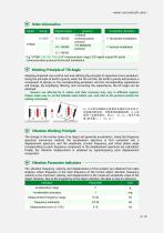
Order Information [vf Working Principle of Tilt Angle Adopting imported core control unit and utilizing the principle of capacitive micro pendulum. Using the principle of Earth's gravity, when the tilt unit tilts, the Earth's gravity will produce a component of gravity on the corresponding pendulum, and the corresponding capacitance will change. By amplifying, filtering, and converting the capacitance, the tilt angle can be obtained. Sensors are affected by G values and their accuracy may vary in different regions. Please make sure to set the latitude value before use, and refer to the protocol...
Open the catalog to page 4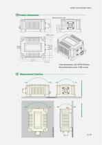
Product Dimensions Case dimensions: L82×W70×H42mm Recommended screws: 4 M6 screws Measurement Direction
Open the catalog to page 6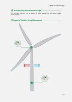
Function Description of Indicator Light The red work indicator light is always on when powered on and flashes during communication. Legend of Vibration Swing Measurement
Open the catalog to page 7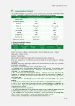
The product includes two protocols: serial communication protocol and MODBUS RTU protocol. The default configuration parameters for the protocols are as follows:_ Default parameters: address 0, baud rate 9600,1 start bit, 8 data, no parity, 1 stop bit. Valid setting address: 0~254; Data length: the length from data length to checksum (including checksum); Data field: according to the different content and length of the command word changes accordingly; Checksum: The sum of data length, address code, command word and data field, regardless of carry, that is, Sum&0xFF. Note, please read the description...
Open the catalog to page 8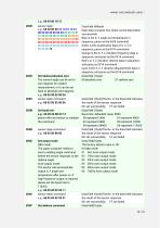
The current angle can be set to zero degrees for relative measurement, or it can be set back to absolute zero degrees. Each data occupies four bytes, as the data below successively Blue is the X, Y angle and temperature in sequence, parse as the 0x04 command Green is the acceleration data of X, Y, Z in sequence, parse as the 0X14 command Orange is the X, Y, Z vibration frequency data in sequence, and parse as the 0X14 command Red is X, Y, Z vibration velocity data in sequence, and parse as 0X14 command Cyan is the X, Y, Z vibration displacement data in sequence, and parse as the 0X14 command...
Open the catalog to page 10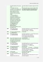
XX module address, the address ranges from 00 to EF. Note: All products have a common address: FF, if you forget the set address during operation, you can use the FF address to operate the product. The default address of the sensor is 00; 1. If multiple sensors are connected to a set of buses at the same time, such as RS485. Each sensor needs to be set to a different address to achieve separate control and response angles. 2. If the new address is successfully changed, all subsequent commands and the address code in the response packet must be changed to the new address code to take effect, otherwise...
Open the catalog to page 11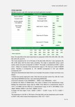
MODBUS function code 03H, read data command application example 1: Note: The data field of the slave reply frame is composed of 50H, 46H, 00H, 00H, 23H, 20H, 00H, 00H, 03H, and 57H The X-axis represents the 1st to 4th bytes of the data field, while the Y-axis represents the 5th to 8th bytes, with the lower bytes preceding. The angle is represented using a point system, where one point corresponds to 0.0001°. The angle is calculated as 0.0001 x (point count - offset). For example, if the measurement range is ±10°, there are a total of 200,000 points. Therefore, 0 corresponds to -10°, 200,000 corresponds...
Open the catalog to page 14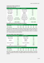
5.Set the sensor relative / absolute zero: MODBUS function code 06H Note: 0011H is the register address, this register controls the sensor address. In the above example, the address of the sensor is changed to 0004H, and the last two bytes are the CRC checksum.
Open the catalog to page 15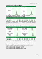
7.Set sensor baud rate : (factory default 9600bps) The above example is to set the byte format to: one start bit + 8 data bits, no parity, + 1 stop bit It is effective after power-on again. The factory default is one start bit + 8 data bits, even parity check + 1 stop bit Note: 0009 is Register Address, which controls the parity bit of the sensor serial port. 0000H: One start bit + 8 data bits, even parity +1 stop bit 0001H: One start bit + 8 data bits No parity + 1 stop bit 0002H: One start bit + 8 data bits, odd parity check + 1 stop bit
Open the catalog to page 16
9.Set sensor output mode: (factory default 0HZ)
Open the catalog to page 17
Set sensor filter length command example: Note: 000EH is Register Address, which controls the filter length of the sensor. In the above example, the sensor filter length is set to 32, and the last two bytes are the CRC checksum. Note: After setting the filtering length, it needs to be powered on again to take effect. Web:www.ruicomtech.com Tel:0755-23087719 E-mail:[email protected] Add:Building 1, Lixin Lake Creative Park, 1 Furui Rd, Fuhai St, Bao'an, Shenzhen, China
Open the catalog to page 18All Shenzhen Ruicom Technology Co., Ltd. catalogs and technical brochures
 STSL Low-Power Tilt Sensor
21 Pages
 STS STANDARD OUTPUT TILT SENSOR
13 Pages
 HTS3D High-Precision Tilt Sensor
15 Pages
 GDS8 Series Digital inclinometer
13 Pages














- Display module
- Industrial display panel
- Color display panel
- Tilt sensor
- Digital inclination sensor
- Built-in display
- 2-axis tilt sensor
- MEMS inclination sensor
- Multi-axis tilt sensor
- Analog inclination sensor
- RS-485 display panel
- High-precision tiltmeter
- IP67 inclination sensor
- 1-axis tilt sensor
- Vibration sensor
- Rugged inclination sensor
- High-resolution inclinometer
- 2" display
- Angle measurement inclination sensor
- RS-485 inclinometer