
- Catalogs
- Shenzhen Ruicom Technology Co., Ltd.
- STS STANDARD OUTPUT TILT SENSOR

STS STANDARD OUTPUT TILT SENSOR

STS STANDARD OUTPUT TILT SENSOR
The STS standard output tilt sensor by RUICOM Technology is engineered for industrial automation control. It features a compact design, RS485/RS232 communication interfaces, a high-performance MEMS tilt sensing unit, and a 24-bit high-precision differential A/D converter. It employs a fifth-order digital filtering algorithm for accurate horizontal and pitch angle measurements, making it suitable for high-precision industrial applications.
This sensor is ideal for building structural health monitoring, industrial automation control systems, and environments requiring long-term stable monitoring in high-precision angle measurement applications.
- Single/dual-axis measurement
- Measurement range: ±180°
- Accuracy: 0.01°
- Industrial-grade reliability
- Multiple standard output interfaces
The sensor offers various measurement ranges (±10° to ±180°) with a resolution of 0.001°. It operates within a temperature range of -40 to 85°C and supports TTL, RS232, and RS485 output signals. It complies with EN61000 and GBT17626 standards for electromagnetic compatibility and has a waterproof rating of IP67.
The sensor dimensions are L62 × W52 × H28 mm, and it uses 4 M4 screws for installation. It includes a standard 2-meter M12 aviation plug with a PVC shielded cable.
The sensor supports serial communication and MODBUS RTU protocols. The serial protocol uses a data frame format with specific command words for operations like reading angles, setting zero points, and adjusting communication speed. The MODBUS protocol requires a 10ms idle time between data frames and supports commands for setting addresses and zero points.
To configure the sensor, enter the settings mode, adjust parameters, save them to FLASH, and exit the mode. The MODBUS protocol allows for setting relative/absolute zero points and querying angle data with specific function codes.
This section describes the process for setting the sensor output to either relative or absolute zero. The command involves sending a specific sequence of bytes from the master computer to the slave computer, which responds with the same sequence. The register address is 0010H. If the value written is nonzero (00FFH), the output is relative zero; if zero, it is absolute zero. The last two bytes are a CRC checksum.
This section outlines the procedure for changing the sensor address. The command must be sent twice to be valid. The register address is 0011H, which controls the sensor's baud rate. The example provided changes the sensor address to 0004H. The last two bytes are a CRC checksum.
This section explains how to set the sensor's baud rate, which defaults to 9600bps. The command must be sent twice to be valid. The register address is 0012H. The example sets the baud rate to 19200bps. The last two bytes are a CRC checksum. Available baud rates are 4800, 9600, 19200, 38400, and 115200.
This section details the command for setting the sensor's communication character format. The register address is 0009H. The example sets the format to one start bit, 8 data bits without parity, and one stop bit. This setting becomes valid after the sensor is powered on again. The factory default includes even parity.
Catalog excerpts

STS STANDARD OUTPUT TILT SENSOR Product manual V1.1-20250226
Open the catalog to page 1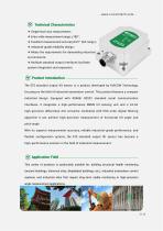
Technical Characteristics ❖ Single/dual-axis measurement; ❖ Extra-wide measurement range: ±180° ; ❖ Excellent measurement accuracy:0.01° (full range ); ❖ Industrial-grade reliability design; ❖ Meets the requirements for demanding industrial environments; ❖ Multiple standard output interfaces facilitate system integration and expansion. Product Introduction The STS standard output tilt sensor is a product developed by RUICOM Technology, focusing on the field of industrial automation control. This product features a compact industrial design. Equipped with RS485/ RS232 standard serial communication...
Open the catalog to page 2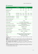
Measurement range Measuring axis Resolution o MAXE RMSE Zero-point temp coefficient Sensitivity temp coefficient Power-on startup time Response frequency Output signal Communication Protocol Electromagnetic compatibility Mean Time Between Failures Serial communication protocol / MODBUS RTU Protocol Optional Impact resistance 100g@11 ms, triaxial (half-sine wave) bl Standard 2-meter M12 aviation plug with PVC ca e shielded cable, wire weight < 120g weight < 150g (excluding cable) Resolution: Refers to the sensor in measuring range to detect and identify the smallest changed value. MAXE: refers...
Open the catalog to page 3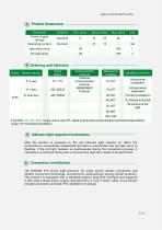
Power supply voltage Operating current Operating temp Storage temp Typical value Max value [Vj Indicator light operation instructions- After the product is powered on, the red indicator light remains on. When the connection is successfully established and data is transmitted, the red light turns to flashing. If the red light remains on continuously during the connection process, it indicates a connection failure and a reconnection operation needs to be performed. Connection Installation- The RUICOM STS series high-precision tilt angle sensor adopts convenient and reliable connection technology,...
Open the catalog to page 4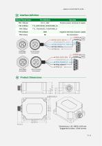
Interface definition Stitch/Thread Color Positive power terminal of supply negative terminal of power supply Product Dimensions Dimensions: L62 ×W52× H28 mm Suggested screws: 4 M4 screws
Open the catalog to page 5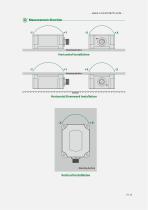
Measurement direction Mounting Surface Horizontal Installation Mounting Surface
Open the catalog to page 6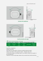
Serial communication protocol- I. Data Frame Format: ( 8 data bits),] stop bit No verification (Default speed 9600) Data format: Hexadecimal; Data length: From data length to checksum (including checksum)Length; Address code: Address of the acquisition module. The default value is 00; The data field changes accordingly based on the different contents and lengths of the command word; Checksum: The sum of data length, address code, command word, and data field does
Open the catalog to page 7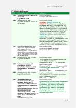
II. Command Word Parsing
Open the catalog to page 8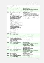
power-off memory) 0X8C Sensor response reply command pata pomain (1byte) E.g: 68 05 00 8C 00 91 The numbers in the data domain represent the results of the sensor response 00 Success FF Failure XX module address, ranging from 00 to EF. Note: All products have a common address: FF. If you forget the set address during operation, you can use the FF address to operate the product and still respond normally. Note: It takes effect immediately after setting (but not saved to FLASH). 0X0F Set module address command The default address of the sensor is 00, 1. If multiple sensors are connected to a group...
Open the catalog to page 9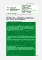
You must first enter the settings mode before entering and saving the settings 1. Enter settings mode ^ Send command: 68 04 00 51 55 A Set address code B Set baud rate C Set calibration parameters D Automatic or inquiry mode E Relative zero point 3. Save parameters and write all parameters to FLASH ^ Send command: 68 04 00 53 57. 4. Exit the setting mode ^ Send command: 68 04 00 52 56. Please read the following items carefully before use: 1> Because of the MODBUS protocol stipulates between the two data frames should be at least more than 3.5 bytes of time (such as the baud rate of 9600, the...
Open the catalog to page 10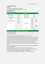
Communication Parameter: Baud rate 9600 bps Data frames: 1 Start bit,8 data,even parity check,1 stop bit Modbus function code 03H Note: The slave reply frame are 5AH, 60H, 01H, 00H, 47H, 62H, 01H, 00H The X-axis is the 1-4 bytes of the data field, the Y-axis is the 5-8 bytes of the data field, and the low byte is first. The representation method of the angle is the number of points notation, one point corresponds to 0.001°, and 0.001x(number of points-offset) is the angle. If the measurement range is +-180°, the total number of points is 360000 points. So 0 corresponds to -180°, 360000 corresponds...
Open the catalog to page 11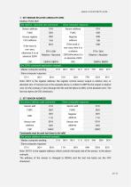
1. SET SENSOR RELATIVE /ABSOLUTE ZERO Set relative / absolute zero command : Slave computer response: Sensor address FUNC Access register First address If the word is non-zero, otherwise it is an absolute ZERO Sensor address FUNC Register address If the word is non-zero, then it is a relative ZERO,otherwise it is an absolute ZERO Set ZERO command application example : Master computer sending 01 H 06 H 00 H 10 H 00 H FFH C8H 4FH Slave computer response Commands must be sent two times to be valid Set sensor address command example : Master computer sending 01 H 06 H 00 H 11 H 00 H 04H D8H 0CH Slave...
Open the catalog to page 12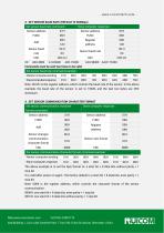
3. SET SENSOR BAUD RATE (DEFAULT IS 9600bps) The above example is to set the byte format to: a start bit + 8 data bits without parity + 1 stop bit It is valid after power on again. The factory default is a start bit + 8 data bits, even parity + 1 stop bit Note: 0009 is the register address, which controls the character format of the sensor communication. 0000H: one start bit + 8 data bits, even parity + 1 stop bit 0001H: one start bit + 8 data bits without parity + 1 stop bit Add:Building 1, Lixin Lake Creative Park, 1 Furui Rd, Fuhai St, Bao'an, Shenzhen, China
Open the catalog to page 13All Shenzhen Ruicom Technology Co., Ltd. catalogs and technical brochures
 STSL Low-Power Tilt Sensor
21 Pages
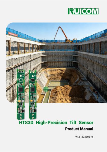 HTS3D High-Precision Tilt Sensor
15 Pages
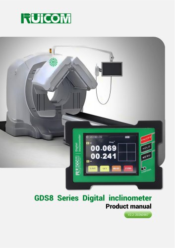 GDS8 Series Digital inclinometer
13 Pages



















- Display module
- Industrial display panel
- Color display panel
- Tilt sensor
- Digital inclination sensor
- Built-in display
- 2-axis tilt sensor
- MEMS inclination sensor
- Multi-axis tilt sensor
- Analog inclination sensor
- RS-485 display panel
- High-precision tiltmeter
- IP67 inclination sensor
- 1-axis tilt sensor
- Vibration sensor
- Rugged inclination sensor
- High-resolution inclinometer
- 2" display
- Angle measurement inclination sensor
- RS-485 inclinometer