
- Catalogs
- Shenzhen Ruicom Technology Co., Ltd.
- RUICOM SWR14X SWR14D Tilt Switch Tilt Sensor


- Company
- Products
- Catalogs
- News & Trends
- Exhibitions
RUICOM SWR14X SWR14D Tilt Switch Tilt Sensor
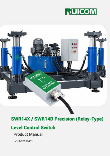
RUICOM SWR14X SWR14D Tilt Switch Tilt Sensor
The SWR14X/SWR14D is a digital tilt switch designed for safety-critical leveling and platform-stabilization applications. It features a relay output for flexible operation, allowing users to set custom alarm thresholds. When the tilt angle exceeds the safety limit, the device triggers a relay contact to actuate solenoid valves, ideal for construction vehicles and aerial platforms. It includes dual-stage compensation for temperature and linearity, ensuring high accuracy, and protection against electrical disturbances. Built with industrial-grade components, it is suitable for harsh environments.
Key Features
- 0.01° resolution
- Dual-axis tilt measurement
- RS232 serial output
- Zero-setting function
- IP67 protection rating
- Selectable relay output (NO/NC)
- User-configurable alarm angle thresholds
Application Scope
This product is suitable for various industrial applications, including agricultural machinery, construction equipment, aerial work platforms, and more.
Performance Parameters
- Measurement Range: ±15°
- Resolution: 0.01°
- Measurement Accuracy: 0.05°
- Temperature Coefficient: ±0.006°/°C
- Startup Time: 0.1s
- Response Time: 0.2s
- EMC: EN 61000 and GB/T 17626 compliant
- MTBF: ≥98,000 hours
- Shock Resistance: 100g @ 11ms
- Vibration Resistance: 10grms, 10–1000Hz
- Waterproof Rating: IP67 (direct-wired), IP65 (aviation connector)
Electrical Parameters
- Supply Voltage: 9-36V
- Alarm Output Current: 500mA
- Operating Temperature: -40 to +85°C
Ordering and Selection
Models are defined by measurement axis, output type, and angle threshold. Example: SWR14X1-NO-005 indicates X-axis, single-channel output, normally open relay, 0.5° alarm threshold.
Interface Definition
Details the wiring and connection for different configurations, including RXD and TXD lines for computer connection to configure alarm thresholds.
Instructions for Use
Explains the operating principle of the dual-axis tilt switch and how to set a relative angle (zeroing).
Installation Orientation
Provides guidelines for sensor installation to ensure accurate measurement.
Debugging Software
Instructions for using serial debugging software to modify alarm thresholds and display angle data.
Communication Protocol
Details the data frame format and configuration commands for setting alarm points and zeroing the device.
Catalog excerpts
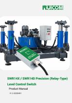
SWR14X / SWR14D Precision (Relay-Type) Level Control Switch Product Manual V1.3-20250401
Open the catalog to page 1
Dynamic Sensing · Precision Measurement and Control Product Introduction The SWR14X/SWR14D is a digital tilt switch specifically developed for safety-critical leveling and platform-stabilization applications. It features an integrated relay output, offering flexible and convenient operation. Users can define custom alarm thresholds; when the tilt angle exceeds the preset safety limit, the device triggers a passive relay contact (with a 1A drive current). This can directly actuate solenoid valves to control hydraulic leveling jacks, making it an ideal solution for equipment such as construction...
Open the catalog to page 2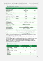
Dynamic Sensing • Precision Measurement and Control Performance Parameters
Open the catalog to page 3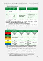
Dynamic Sensing • Precision Measurement and ControlOrdering and Selection Measure Axis Type NO: Relay normally Setting the output angle open output threshold: 2: Dual D: Dual °u,put NC: Relay normally closed output Any value within the 0-30° range can be entered. Examples: 005 = 0.5° (triggers alarm); Example: SWR14X1 -NO-005: X-axis, single-channel output, normally open (NO) relay output, 0.5° alarm threshold. Notes: 1)Wire color-to-function assignments vary by model; please refer to the model descriptions in the ordering information before placing an order. 2) Default factory alarm threshold:...
Open the catalog to page 4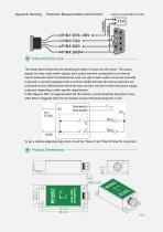
Dynamic Sensing · Precision Measurement and Control Instructions for Use The image above illustrates the operating principle of a dual-axis tilt switch. The output signals are relay-style switch signals; each output terminal corresponds to an internal switch (indicated within the dashed box), with one side of each switch connected internally to ground. In versions equipped with a common (COM) terminal, the internal switches are connected to this COM terminal, which the user can then connect to either the power supply or ground, depending on their specific requirements. In this diagram, MG1 is...
Open the catalog to page 5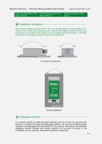
Dynamic Sensing · Precision Measurement and Control Enclosure dimensions: L90 × W40 × H26 mm - www.ruicomtech.com Mounting screws: 4 × M6 screws Installation Orientation Note: During installation, ensure that the sensor’s mounting surface remains parallel to the surface of the target being measured; also, minimize the impact of dynamic forces and acceleration on the sensor. This product can be installed either horizontally or vertically; please refer to the diagrams below for mounting configurations. Debugging software If a customer wishes to modify the alarm threshold, this can be done by connecting...
Open the catalog to page 6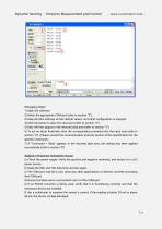
Dynamic Sensing • Precision Measurement and Control Debugging Steps: 2) Select the appropriate COM port (refer to section "2"). 3) Keep all other settings at their default values; no further configuration is required. 4) Click the button to open the serial port (refer to section "2"). 5) Data will then appear in the returned data area (refer to section "3"). 6) To set an alarm threshold, enter the corresponding command into the input area (refer to section "4"). (Please consult the communication protocol section of this specification for the specific command.) 7) If "Command + Okay" appears in...
Open the catalog to page 7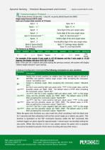
Dynamic Sensing · Precision Measurement and Control Communication Protocol 1: Data frame format: (8 data bits, 1 stop bit, no parity, default baud rate 9600) Angle output format (ASCII code) Each set of output data consists of 18 bytes: Byte1:X Tens digit of the axis angle value Units digit of the axis angle value Byte 14: Decimal point "." Tenths digit of the axis angle value Byte 5: Decimal point "." Byte6:X Hundredths digit of the axis angle value Byte 17: Carriage return (0x0D) Byte 18: Line feed (0x0A) Byte 8: Space (0x20) Byte 9: Space (0x20) The format is as follows: ITEAM SIGNED DATA...
Open the catalog to page 8All Shenzhen Ruicom Technology Co., Ltd. catalogs and technical brochures




































- Tilt sensor
- Digital inclination sensor
- 2-axis tilt sensor
- MEMS inclination sensor
- Multi-axis tilt sensor
- High-precision tiltmeter
- Analog inclination sensor
- IP67 inclination sensor
- 1-axis tilt sensor
- Vibration sensor
- Rugged inclination sensor
- Waterproof tiltmeter
- Angle measurement inclination sensor
- High-resolution inclinometer
- RS-485 inclinometer
- Inclination sensor with aluminum housing
- RS-232 inclinometer
- Anti-vibration inclinometer
- CAN inclination sensor