
- Catalogs
- Shenzhen Ruicom Technology Co., Ltd.
- RUICOM NTS6 Series Digital Tilt Sensor


- Company
- Products
- Catalogs
- News & Trends
- Exhibitions
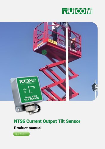
RUICOM NTS6 Series Digital Tilt Sensor
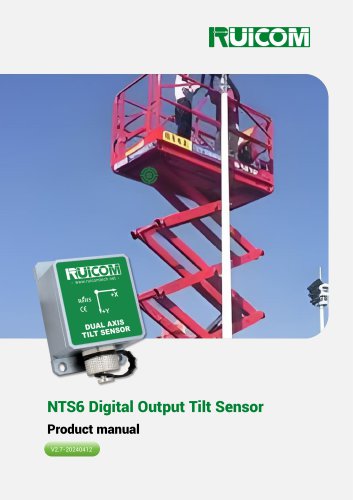
RUICOM NTS6 Series Digital Tilt Sensor
Application Scope: This inclinometer is used in industrial applications such as machinery angle control, automobile alignment, chassis measurement, medical bed leveling, gimbal operation monitoring, and satellite antenna positioning.
Technical Highlights: The device offers single/dual axis tilt measurement with a selectable range of ±10~±90°, a resolution of 0.02°, a standard DC 5V power supply, and an IP67 protection rating.
Performance Parameters: It provides a measurement range of ±10° to ±90°, with a resolution of 0.02° and accuracy of 0.1° at 25°C. It features a zero-point temperature coefficient of ±0.02°/°C and a sensitivity temperature coefficient of ≤150 ppm/°C. The startup time is 0.5 seconds, with a response frequency of 20 Hz and configurable output rates.
Ordering and Selecting: The model can be customized based on housing, axis, range, signal output protocol, and installation method. For example, NTS3X10-C1-H indicates a PCBA, X-axis, ±10° range, CANopen output, and horizontal installation.
Interface Definition: The sensor uses a 5-pin connector with specific wire colors for power supply and data transmission.
Electrical Parameters: It operates on a power supply voltage of 4.5 to 5.5 V (standard) or 9 to 36 V (customizable), with varying operating currents depending on the voltage. It functions within a temperature range of -40 to +85°C.
Product Dimensions: The PCBA board measures L32.7×W27×H8.2mm, while the shell dimensions are L55.5×W37×H29mm, made of anodized aluminum.
Instructions for Use: The sensor should be installed with its sensing axis parallel to the tilt axis of the object. It can be installed on any of its six sides and has an IP67 protection rating. Care should be taken to avoid short-circuiting during installation.
Installation Orientation: The sensor can be installed horizontally or vertically, with specific instructions provided for minimizing dynamic and acceleration effects.
SP: Serial Communication Protocol: The data frame format includes an identifier, data length, address code, command word, data field, and checksum. Various command words are used for angle reading, zero-point setting, communication rate setting, output mode setting, and module address setting.
MB: MODBUS Communication Protocol: The protocol requires a minimum time interval between data frames and specifies the use of broadcast addresses for certain operations. Commands must be sent consecutively for settings to be effective, and the communication indicator light flashes after successful communications.
Overview: This document provides technical instructions for configuring sensor settings, including setting relative/absolute zero points, sensor addresses, baud rates, and automatic output frequencies.
1. Setting Relative/Absolute Zero Point: The register address 0010H controls whether the sensor output is a relative zero or an absolute zero. Example command: Master sends 01H 06H 00H 10H 00H FFH C8H 4FH; Slave replies with the same.
2. Setting the Sensor Address: The register address 0011H is used to change the sensor address. Example command: Master sends 01H 06H 00H 11H 00H 04H D8H 0CH; Slave replies with the same.
3. Setting the Sensor Baud Rate: The register address 0008H controls the sensor baud rate. Baud rate options include 4800 (A0H), 9600 (A1H), 19200 (A2H), 38400 (A3H), and 115200 (A4H). Commands must be sent twice consecutively to be effective. Example command: Master sends 01H 06H 00H 08H 00H A2H A8H 76H; Slave replies with the same.
4. Setting Automatic Output Frequency: The register address 0013H controls the sensor's automatic output frequency. Frequency options include 0 (Inquiry mode), 1 (10Hz), 2 (25Hz), and 3 (50Hz). Example command: Master sends 01H 06H 00H 13H 00H 00H 78H 0FH; Slave replies with the same.
Contact Information: Website: www.ruicomtech.com, Email: [email protected], Phone: 0755-23087719, Address: Building 1, Lixin Lake Creative Park, 1 Furui Rd, Fuhai St, Bao'an, Shenzhen, China.
Catalog excerpts

Product manual
Open the catalog to page 1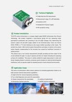
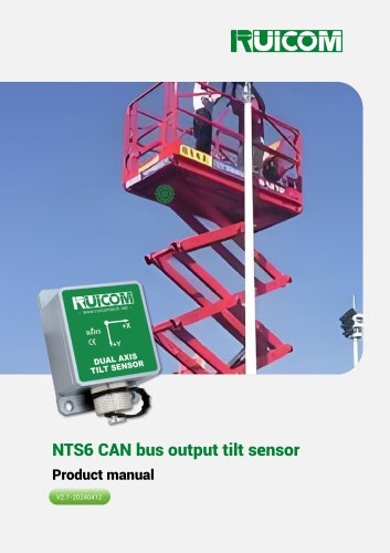
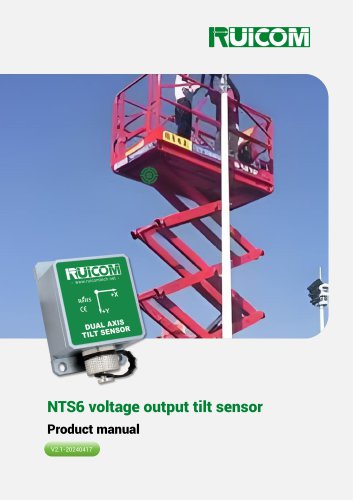
[v> Technical Highlights ❖ Single/dual axis tilt measurement; ❖ Standard DC 5V power supply; The NTS6 series inclinometer is a compact digital output MEMS inclinometer from Ruicom Technology. This product integrates a dual-channel gravity tilt unit, measuring static gravitational acceleration and converting it into tilt angle changes, thus determining the sensor's output roll and pitch angles relative to the horizontal plane. Users can choose RS232, RS485, or TTL level interfaces as the output method according to their needs. The product has a built-in MCU control system that performs secondary...
Open the catalog to page 2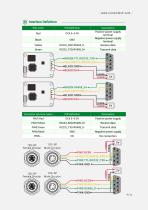
Wire color
Open the catalog to page 4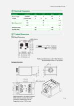
Electrical Parameters Parameter Power supply voltage Operating current Operating temp Storage temp Product Dimensions PCBA Board Dimensions PCBA board dimensions: L32.7×W27×H8.2mm Recommended screws: 4 -M3 screws Package dimensions Shell dimensions: L55.5×W37×H29mm Shell material: anodized aluminum Connector: aviation plug 12G-5P Suggested screws: 3 M4 screws
Open the catalog to page 5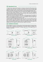
Instructions for use 1. This tilt sensor measures the tilt angle of an object by sensing the Earth's gravity. During installation, ensure the sensor's sensing axis is parallel to the tilt axis of the object being measured for optimal accuracy. The sensor and the surface being measured must be tightly fitted, flat, and stable. Uneven mounting surfaces can cause measurement angular errors. 2. This tilt sensor can be installed on any of its six sides. After installation, use the sensor's relative zero-point setting command to zero it. (This also sets the current installation method; the setting...
Open the catalog to page 6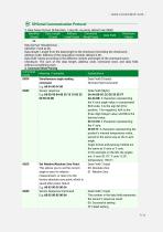
SRSerial Communication Protocol 1. Data frame format: (8 data bits, 1 stop bit, no parity, default rate 9600) Data format: Hexadecimal, Data length: Length from the data length to the checksum (including the checksum), Address code: Address of the acquisition module, default is 00, Data field: Varies according to the different content and length of the command word, Checksum: The sum of the data length, address code, command word, and data field, without considering carry. 2. Command Word Parsing__ Simultaneous angle reading Sensor response Set Relative/Absolute Zero Point: This allows you to...
Open the catalog to page 7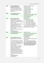
This command setting requires a power failure and restart to take effect, and the setting is saved after power failure. Set Sensor Output Mode Response Mode: The sensor responds with a relative angle only after the host computer sends a read angle command. Automatic Output Mode: The sensor automatically outputs X and Y angles after power-on, with the output frequency set as shown in the table on the right. (This function is power-off memory saved) Set module address command The default address of the sensor is 1. If multiple sensors are connected to a bus, such as RS485, each sensor needs to...
Open the catalog to page 8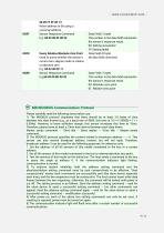
Please carefully read the following items before use: 1) The MODBUS protocol stipulates that there should be at least 3.5 bytes of time between two data frames (e.g., at a baud rate of 9600, this time is 3.5 x (1/9600) x 11 = 0. 004.). However, to leave sufficient margin, this sensor increases this time to 10ms. Therefore, please leave at least a 10ms time interval between each data frame. Master sends command -- 10ms idle -- Slave replies -- 10ms idle -- Master sends command... 2) The MODBUS protocol specifies the content related to broadcast address----0. This sensor can also receive broadcast...
Open the catalog to page 9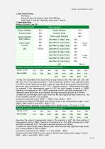
- www.ruicomtech.com -1. Data Frame Format: Communication Parameters: Baud Rate 9600 bps Data Frame: 1 start bit, 8 data bits, even parity, 1 stop bit 2. Read Angle Data: Modbus Function Code 03H Assuming the sensor's measurement range in this example is ±45°, the total number of measurement points is 9000. Therefore, 0 corresponds to -45°, 9000 corresponds to +45°, and 4500 corresponds to 0°. The angle conversion process is as follows: 1) Obtain the current angle measurement points. Note that the least significant byte comes first: X-axis is 0000H, Y-axis is 2300H. 2) Convert to decimal: X-axis:...
Open the catalog to page 10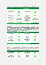
4) Obtain the final angle: X-axis: -4500 x 0.01 = -45.00°, Y-axis: 4460 x 0.01 = 44.60°. 3. Setting the sensor’s relative/absolute zero point: (Modbus function code 06H)
Open the catalog to page 11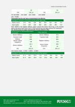
Web: www.ruicomtech.com E-mail: [email protected] Add:Building 1, Lixin Lake Creative Park, 1 Furui Rd, Fuhai St, Bao'an, Shenzhen China
Open the catalog to page 12All Shenzhen Ruicom Technology Co., Ltd. catalogs and technical brochures


































- Display module
- Industrial display panel
- Acceleration sensor
- Color display panel
- Digital inclination sensor
- Triaxial acceleration sensor
- Built-in display
- 2-axis tilt sensor
- Multi-axis tilt sensor
- High-precision tiltmeter
- Analog inclination sensor
- IP67 inclination sensor
- Industrial accelerometer
- 1-axis tilt sensor
- MEMS accelerometer
- RS-485 display panel
- Accelerometer with built-in electronics
- Vibration sensor