
- Catalogs
- Shenzhen Ruicom Technology Co., Ltd.
- Ruicom NTS3 Series CANBUS output tilt sensor


- Company
- Products
- Catalogs
- News & Trends
- Exhibitions
Ruicom NTS3 Series CANBUS output tilt sensor
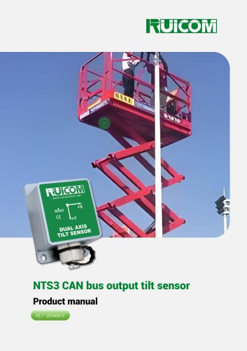
Ruicom NTS3 Series CANBUS output tilt sensor
The NTS3 series is a digital miniature MEMS tilt sensor developed by RUICOM Technology. It measures static gravitational acceleration to determine roll and pitch angles relative to the horizontal plane. It supports CAN OPEN, CAN2.0A, and CAN2.0B protocols, with a built-in MCU for improved accuracy. It is suitable for static or slowly changing environments and offers resistance to electromagnetic interference.
Application Scope
Applications include angle control for machinery, satellite antenna positioning, automobile alignment, medical bed leveling, and gimbal operation monitoring.
Technical Highlights
- Selectable outputs: CANopen/CAN2.0A/CAN2.0B
- Measurement range: ±10° to ±90°
- Resolution: 0.02°
- Power supply: DC 5V
- Protection rating: IP67
Performance Parameters
Measurement ranges vary from ±10° to ±90° with a resolution of 0.02° and accuracy of 0.1° at 25°C. The sensor has a response frequency of 20 Hz and configurable output rates. It is compatible with EN61000 and GBT17626 standards for electromagnetic compatibility.
Ordering and Selecting
Models are defined by housing type, axis, range, signal output, and installation method. For example, NTS3X10-C1-H indicates a shell housing, X-axis, ±10° range, CANopen output, and horizontal installation.
Electrical Parameters
Standard power supply voltage is 4.5-5.5V, with customizable options up to 36V. Operating temperature ranges from -40°C to +85°C.
Interface Definition
Wire colors and pin definitions are provided for power supply and CAN communication lines.
Product Dimensions
The PCBA board measures L33 × W27 × H8.2 mm, while the shell dimensions are L55.5×W37×H29mm, made of anodized aluminum.
Installation Orientation
The sensor should be installed parallel to the target surface, minimizing dynamic and acceleration effects. It can be installed horizontally or vertically.
CANOPEN Communication Protocol
Details on SDO messages, node number modification, baud rate settings, and PDO sending time are provided. The sensor outputs angles immediately upon power-up, with specific message formats for data transmission.
CAN2.0A/B Communication Protocol
Similar to CANOPEN, this section details node number modification, baud rate settings, and angle data analysis. The sensor outputs angles with a specific message format, and conversion examples are provided.
Catalog excerpts
Product manual
Open the catalog to page 1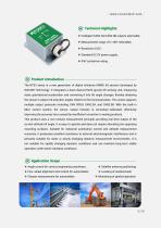
Technical Highlights ❖ Measurement range ±10~±90° selectable; ❖ Standard DC 5V power supply; Product Introduction- The NTS3 series is a new generation of digital miniature MEMS tilt sensors developed by RUICOM Technology. It integrates a dual-channel Earth gravity tilt sensing unit, measuring static gravitational acceleration and converting it into tilt angle changes, thereby obtaining the sensor's output roll and pitch angles relative to the horizontal plane. This series supports multiple output protocols including CAN OPEN, CAN2.0A, and CAN2.0B. With the built-in MCU control system, the sensor...
Open the catalog to page 2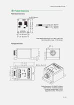
Product Dimensions PCBA Board Dimensions PCBA board dimensions: L33 × W27 × H8.2 mm Recommended screws: 4 × M3 screws Package dimensions Shell dimensions: L55.5×W37×H29mm Shell material: anodized aluminum Connector: aviation plug 12G-5P Suggested screws: 3 M4 screws
Open the catalog to page 5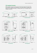
Installation Orientation During installation, the sensor mounting surface should be kept parallel to the target surface, and the effects of dynamics and acceleration on the sensor should be minimized. This product can be installed horizontally or vertically; please refer to the diagram below for installation instructions:
Open the catalog to page 6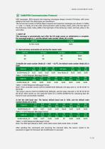
SDO messages: SDO request and response messages always consist of 8 bytes, with zeros added at the end if the data bytes are insufficient. The format and content of Write Object request and response messages are shown in Tables 1-1 and 1-2: Node_ID is the CAN communication node number, Index_LSB is the low byte of the dictionary index, Index_MSB is the high byte of the dictionary index, and Sub_index is the sub-index. This message is automatically sent after the tilt angle power-on initialization is complete. The message length is 1, and the default node number (Node_ID) is 0x05._ Table 1 -5...
Open the catalog to page 7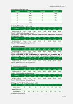
Baud corresponding baud rate Table 1-11 SDO Request Message Format Table 1-12 SDO Response Message Format 8) Change the PDO ID. The default value is 0x285. Reply command
Open the catalog to page 8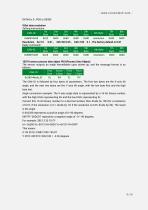
Setting instructions: The CAN-ID is followed by four bytes of parameters. The first two bytes are the X-axis tilt angle, and the next two bytes are the Y-axis tilt angle, with the low byte first and the high byte last. Angle conversion example: The X-axis angle data is represented by a 16-bit binary number, with the high 8 bits representing XH and the low 8 bits representing XL. Convert this 16-bit binary number to a decimal number, then divide by 100 (for a resolution of 0.01; if the resolution is 0.1, divide by 10; if the resolution is 0.05, divide by 20). The result is the angle. 0-0X2328...
Open the catalog to page 9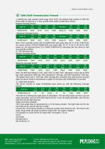
1) Modify the node number (node range: 0x01-0x7F), the default node number is 0x05.The ID bit width of CAN2.0A is 11 bits, and the ID bit width of CAN2.0B is 29 bits. Request message format_______ Note: If the controller sends CAN-ID=0x600+0x05 and sends data: 40 10 10 00 10 00 00 00, the sensor returns CAN-ID=0x580+0x05 and sends data: 40 10 10 00 10 00 00 00. After power-on, the received frame ID is 0x590 (0x580+0x10), indicating that the frame ID was successfully modified. Request message format________ The CAN-ID is followed by eight bytes of parameters. The first three bytes are the X-axis...
Open the catalog to page 10All Shenzhen Ruicom Technology Co., Ltd. catalogs and technical brochures














- Tilt sensor
- Digital inclination sensor
- 2-axis tilt sensor
- MEMS inclination sensor
- Multi-axis tilt sensor
- High-precision tiltmeter
- Analog inclination sensor
- IP67 inclination sensor
- 1-axis tilt sensor
- Vibration sensor
- Rugged inclination sensor
- Waterproof tiltmeter
- Angle measurement inclination sensor
- High-resolution inclinometer
- Tilt switch
- RS-485 inclinometer
- Inclination sensor with aluminum housing
- RS-232 inclinometer
- Anti-vibration inclinometer
- CAN inclination sensor