
- Catalogs
- Shenzhen Ruicom Technology Co., Ltd.
- RUICOM GCM370-MI-SJ Low Power Consumption High Precision 3D Electronic Compass

RUICOM GCM370-MI-SJ Low Power Consumption High Precision 3D Electronic Compass
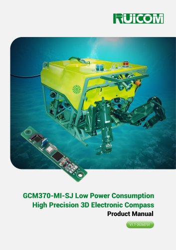
RUICOM GCM370-MI-SJ Low Power Consumption High Precision 3D Electronic Compass
The GCM370-MI-SJ is a 3D electronic compass designed for low power consumption and high precision. It incorporates advanced calibration algorithms and a high-performance accelerometer for tilt compensation, providing reliable heading output over a 360° range. It is ideal for environments with fixed magnetic interference and is commonly used in handheld terminals, mobile devices, and vehicle systems.
This compass is suitable for marine navigation, GPS integrated systems, antenna control, infrared imaging, laser ranging, and specialized robot applications.
- Azimuth accuracy: 0.5°
- Roll angle measurement range: ±180°
- Tilt resolution: 0.1°
- Tilt accuracy: <0.2°
- Standard TTL output interface
- Heading accuracy: 0.5°
- Resolution: 0.1°
- Pitch and roll accuracy varies with measurement range
- Calibration: Hard and soft iron calibration available
- Physical dimensions: L67×W12×H9mm, weight ≤10g
- Output interface: TTL
- Power supply: DC +5V, operating current 5mA
- Operating range: -40℃ to +85℃
- Protection: IP67, compliant with EN61000 and GBT17626
For optimal accuracy, install the compass away from magnetic interference sources. Use copper fasteners and minimize cable length to reduce signal noise. The compass is not suitable for dynamic magnetic field environments.
- Horizontal Installation Calibration: Rotate the compass 360° horizontally and vertically, ensuring each rotation lasts more than 20 seconds.
- Vertical Installation Calibration: Similar to horizontal calibration, but with vertical rotations.
- Multi-point Calibration: Used in constant magnetic interference environments, involving sampling 24 points and requiring a stable installation environment.
1. Start at H=0°, R=-45°, P=0° and hold for 2-3 seconds to acquire the 21st point.
2. Rotate horizontally by 90° and hold for 2-3 seconds to acquire subsequent points (22nd to 24th).
3. Send a stop command to receive scoring data from the compass.
- Protocol: Serial communication
- Address Code: 0
- Broadcast Address: 255
- Baud Rate: 9600
- Parity Bit: None
- Data Bit Length: 8 Bits
- Stop Bit: 1 Bit
- Output Mode: Question-and-answer mode
- Calibration Method: Plane calibration
- Data Verification: Accumulated sum verification
- Geomagnetic Threshold: 0.44/1.4~0.44*1.4
- Identifier: 68H
- Data Length: From data length to checksum
- Address Code: Default 00
- Command Word: Varies
- Checksum: Sum of data length, address code, command word, and data fields
- Read Pitch, Roll, and Heading: Command word 04H
- Set Magnetic Declination: Command word 06H
- Read Magnetic Declination: Command word 07H
- Calibration Method Setting: Command word 2BH 00H
- Calibration Method Query: Command word 2BH01H
- Horizontal Start Calibration: Command Word 41H
- Vertical Upward Calibration: Command Word 42H
- Vertical Downward Calibration: Command Word 43H
- Clear Calibration: Command Word 5AH
- Factory Reset: Command Word 0EH
- Start Calibration: Command Word 08H
- Calibration Stop: Command Word 09H
- Automatic Calibration: Command Word 44H
- Manual Calibration: Command Word 43H
- Manual Data Acquisition: Command Word 45H
- Residual Coefficient: Should be less than 1
- Uniformity: Should be less than 6%
- Tilt Angle Distribution: Between 0 and 1
- Maximum Single-sided Amplitude: Greater than 45°
- Save Calibration Command: Command word 0AH saves calibration settings. The sensor responds with command word 8AH indicating success (00) or failure (FF).
- Calibration Abort Command: Command word 46H stops calibration and reverts to previous settings unless calibration has been saved. Sensor response is command word C6H.
- Set Baud Rate: Command word 0BH sets the communication baud rate with options ranging from 9600 to 115200. Sensor response is command word 8BH.
- Set Module Address: Command word 0FH sets the module address, with a default of FF. Sensor response is command word 8FH.
- Set Angle Output: Command word 0CH configures output mode, including automatic output at various frequencies. Sensor response is command word 8CH.
- Set Geomagnetic Detection Threshold: Command word 50H sets the threshold for interference detection. Sensor response is command word D0H.
- Set Installation Mode: Command word 2AH configures the sensor for vertical or horizontal installation, requiring recalibration. Sensor response is command word AAH.
- Read Accelerometer: Command word 60H retrieves acceleration data for X, Y, and Z axes. Sensor response is command word E0H.
- Read Magnetometer: Command word 61H retrieves magnetometer data for X, Y, and Z axes. Sensor response is command word E1H.
- Enter Low-Power Mode: Command word FAH transitions the sensor to low-power mode. Sensor response is command word AAH.
- Exit Low-Power Mode: Command word EEH wakes the sensor briefly, with automatic re-entry to low-power mode if not a wake-up command. Sensor response is command word EEH.
Catalog excerpts

GCM370-MI-SJ Low Power Consumption High Precision 3D Electronic Compass Product Manual V1.7-20260701
Open the catalog to page 1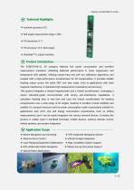
Technical Highlights ❖ Azimuth accuracy: 0.5°; ❖ Roll angle measurement range: ±180°; ❖ Tilt resolution: 0.1°; ❖ Tilt accuracy: <0.2° (full range); ❖ Standard TTL output interface. Product Introduction The GCM370-MI-SJ 3D compass features low power consumption and excellent measurement resolution, exhibiting balanced performance in noise suppression and temperature drift stability. Utilizing mature hard and soft iron calibration algorithms, and coupled with a high-performance accelerometer for tilt compensation, it provides reliable heading output across the entire 360° tool face range. Even...
Open the catalog to page 2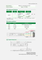
Shock resistance Ordering and Selecting Communication communication protocol E.g: GCM370-TTL-SP-H-MI-SJ: TLL signal output / serial communication protocol / horizontal mounting Interface Definition H: Horizontal installation Line color
Open the catalog to page 4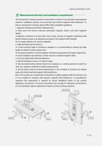
The 3D electronic compass azimuth measurement is based on the principle of geomagnetic induction. Installation requires an environment with minimal magnetic field interference. To ensure measurement accuracy, please follow these installation guidelines: 1. Magnetic Interference Protection Requirements: ❖ Keep away from ferrous materials, permanent magnets, motors, and other magnetic objects. ❖ Maintain a distance of at least 30cm from known sources of magnetic interference (the specific distance needs to be adjusted according to the magnetic field strength). ❖ Use copper fasteners for secure...
Open the catalog to page 5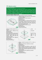
Calibration method Calibration prerequisites: 1) The compass accuracy does not meet the requirements; 2) If there is a fixed magnetic field interference in the compass installation environment (e.g., installed on ferrous materials), the interference source and the compass must be rotated synchronously for calibration, and their relative positions must be kept fixed during use; otherwise, recalibration is required. If the size or distance of the interference source is not fixed (e.g., a variable iron component), calibration is not possible; a safe installation distance of at least 30cm should...
Open the catalog to page 6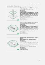
- www.ruicomtech.com Vertical installation calibration mode: Connect the LCM compass correctly to the communication port and turn on the power. 1)Rotate the plane more than 360° in one revolution: As shown in Figure D Horizontal Calibration Start Command 68 04 00 41 45 Data Field (0 bytes) Rotate horizontally at a constant speed for more than one revolution, ensuring the time is more than 20 seconds. Values saved are only valid if the time is more than 20 seconds; values saved are invalid if the time is less than 20 seconds. Horizontal Calibration Save Command 68 04 00 51 55 Data Field (0 bytes)...
Open the catalog to page 7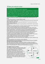
Multi-point calibration method Calibration prerequisites: 1) The compass accuracy does not meet the requirements; 2) The compass installation environment has magnetic field interference. This interference is constant, and the distance between this interfering magnetic field and the compass will not change after installation (e.g., if the compass is installed on iron, the iron will cause magnetic interference. In this case, the iron and compass need to be rotated together for calibration, and they cannot be separated during use; if separated, recalibration is required. If the size of the iron...
Open the catalog to page 8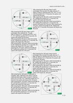
- www.ruicomtech.com After acquiring the 4th point, keep H and R unchanged, then increase the angle value by +P. Refer to Figure B: Starting point H=0°, R=0°, P=+70°. Hold this position for 2-3 seconds; the system will acquire the 5th point. After acquiring the 5th point, rotate horizontally by 90°, holding this position for 2-3 seconds; the system will acquire the 6th point. After acquiring the 6th point, rotate horizontally by 90°, holding this position for 2-3 seconds; the system will acquire the 7th point. After acquiring the 7th point, rotate horizontally by 90°, holding this position for...
Open the catalog to page 9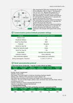
After acquiring the 20th point, increase the roll value (R) for calibration. Refer to Figure F: Starting point H=0°, R=-45°, P=0°. Maintain this posture for 2-3 seconds; the system will acquire the 21 st point. After acquiring the 21 st point, rotate horizontally by 90° and maintain this posture for 2-3 seconds; the system will acquire the 22nd point. After acquiring the 22nd point, rotate horizontally by 90° and maintain this posture for 2-3 seconds; the system will acquire the 23rd point. After acquiring the 23rd point, rotate horizontally by 90° and maintain this posture for 2-3 seconds; the...
Open the catalog to page 10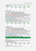
Sensor response (Pitch, Roll, Heading): Command word 0X84 (Response to selecting the standard protocol) Data Field (1 byte) The number in the data field represents the sensor's response.
Open the catalog to page 11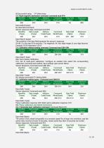
00 Successful setup FF Failed setup 2.3. Read magnetic declination command: command word 07H Data field (1 byte) Planar calibration response: 00H; Multi-point calibration response: 01H 2.6. Planar calibration and related instructions 2.6.1 Horizontal start calibration command: Command Word 41H The sensor must rotate horizontally at a constant speed for at least one revolution, and the saved value must be at least 20 seconds; values saved less than 20 seconds are invalid. Sensor response: Command word 41H
Open the catalog to page 12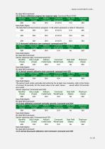
Data field (1 byte) The data field command shows progress 1-128, which represents a total of 128 points.
Open the catalog to page 13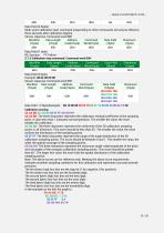
Data Field (0 bytes) Multi-point calibration start command (responding to other commands will only be effective three seconds after calibration begins) Sensor response: Command word 88H SA AA BB: The three characters represent the calibration residual coefficient of the sampling point. A value less than 1 indicates normal operation. The smaller the value, the more reliable the calibration. SC CD DD: The three characters represent the uniformity of the 3D calibration sampling points in all directions. This score should be less than 6%. The smaller the value, the more uniform the distribution of...
Open the catalog to page 15All Shenzhen Ruicom Technology Co., Ltd. catalogs and technical brochures






- Display module
- Industrial display panel
- Color display panel
- Tilt sensor
- Digital inclination sensor
- Built-in display
- 2-axis tilt sensor
- MEMS inclination sensor
- Multi-axis tilt sensor
- High-precision tiltmeter
- Analog inclination sensor
- IP67 inclination sensor
- 1-axis tilt sensor
- RS-485 display panel
- Vibration sensor
- Rugged inclination sensor
- High-resolution inclinometer
- Angle measurement inclination sensor
- RS-485 inclinometer
- 2" display