
- Catalogs
- Shenzhen Ruicom Technology Co., Ltd.
- RUICOM DTS6 CANOpen Dynamic High-Shock-Resistant Tilt Sensor


- Company
- Products
- Catalogs
- News & Trends
- Exhibitions
RUICOM DTS6 CANOpen Dynamic High-Shock-Resistant Tilt Sensor

RUICOM DTS6 CANOpen Dynamic High-Shock-Resistant Tilt Sensor
- Dual-axis measurement range of ±90° with a resolution of 0.01°.
- Dynamic accuracy of ±0.1° and static accuracy of ±0.05°.
- Utilizes CANOpen protocol with three protection levels available.
The DTS6 CANOpen is a high-performance digital MEMS dual-axis dynamic tilt sensor developed by RUICOM Technology. It is designed for real-time attitude monitoring of moving vehicles, optimized for tilt measurement under vibration or motion conditions. The sensor integrates a triaxial accelerometer and gyroscope, using an adaptive Kalman filter algorithm for accurate spatial attitude parameter calculation. It supports real-time tilt data output without the need for planar relative calibration during installation.
Applications include strong impact vibration crushing equipment, engineering vehicle equipment measurement and control, construction equipment leveling, agricultural machinery measurement and control, aircraft attitude control, and ship attitude monitoring.
- Measurement range: X-tilt ±180°, Y-tilt ±90°.
- Gyroscope range: ±300°/s with zero-bias stability of 8.5°/h.
- Acceleration range: ±4g / ±16g (optional).
- Protection class: IP67 / IP68 with anti-corrosion options.
- Power supply voltage: 9-36 V.
- Operating temperature: -40 to +85℃.
The DTS series supports multiple operating modes including Poll, Loop, and Synchronization modes. It operates on a client-server model within a CANopen network, supporting up to 127 devices.
The sensor uses an ENU coordinate system and follows the right-hand rule for defining attitude angles. It includes an M12-5-pin aviation plug connector and a 2-meter black PVC shielded cable.
The device is highly flexible, allowing all parameters to be set via the CAN bus. Factory default configurations can be restored at any time.
Objects in the CANopen protocol for inclinometers are activated based on the state of the device. PDO objects are active in the Operational state, while SDO objects are active in both Pre-Operational and Operational states.
All objects adhere to the CiA-DS410 inclinometer CANopen outline. Command identifiers are provided for inclinometer transmission and reception, facilitating communication analysis between master and slave devices on the CAN bus.
Commands such as Domain Download (22h) and Domain Upload (40h) are used for parameter requests and confirmations. The command data length varies, with specific lengths for different commands (e.g., 43h for 4 bytes).
Objects like 6010h and 6020h are used to obtain dual-axis tilt angles, with ranges of ±90° for X and Y axes. Storage parameters and resolution settings are also configurable, with resolutions ranging from 1º to 0.01º.
PDOs transmit real-time data and are only allowed in Operational mode. The first and second PDO communication parameters are detailed, including sub-index descriptions and default values.
Transmission modes for objects 1800h and 1801h can be cyclic or acyclic, with specific settings for inhibit and event timers. The event timer operates in asynchronous modes, and the cyclic timer is linked to event timers.
SDOs allow explicit data access requests, available in Operational or Pre-Operational states. They follow a client/server model for downloading and uploading data.
Various objects like Device Type (1000h), Error Register (1001h), and COB-ID Synchronization (1005h) are described, detailing their functions, data types, and default values. Objects for storing and restoring parameters (1010h and 1011h) are also included.
Objects like Manufacturer's Equipment Name (1008h) and Hardware Version (1009h) provide device-specific information, including names and version details.
Objects like Consumer Heartbeat Time (1016h) and Identifier Object (1018h) define heartbeat cycles and provide general identifiers for the inclinometer.
Objects like Preset X-Axis (2600H) and Save Parameter With Reset (2300h) allow setting axis values and saving parameters in non-volatile memory, with specific access codes and preset ranges.
- Parameters: 1011.4 is a Read/Write Unsigned 32-bit object.
- COB-ID Emergency: 1014 is a Read-only Unsigned 32-bit object.
- Consumer Heartbeat Time: 1016 is an ARRAY with Sub 0 as Read-only Unsigned 8 and Sub 1 as Read/Write Unsigned 32.
- Producer Heartbeat Time: 1017 is a Read/Write Unsigned 16-bit object.
- Identity Object: 1018 is a RECORD with multiple sub-entries including Vendor ID, Product Code, Revision Number, and Serial Number, all Read-only Unsigned 32-bit objects.
- TxPDO1 Comm Parameter: 1800 is a RECORD with entries for COB-ID, Transmission Type, Inhibit Time, and Event Timer.
- TxPDO2 Comm Parameter: 1801 is similar to 1800 with the same structure.
- TxPDO1 Mapping: 1a00 is a RECORD with mapped objects.
- TxPDO2 Mapping: 1a01 is similar to 1a00.
- Cyclic Time: 2200 is a Read/Write Unsigned 16-bit object.
- Store Parameters: 2300 is a Write-only Unsigned 32-bit object.
- Preset Axes: X-Axis 2600 and Y-Axis 2601 are Read/Write Signed 16-bit objects.
- Node Number and Baud Rate: 3000 and 3001 are Read/Write Unsigned 8-bit objects.
- Moving Average Filter: 3100 is a Read/Write Unsigned 16-bit object.
- Gyro and Acceleration: Gyro and acceleration data for x, y, and z axes are Read-only Signed 16-bit objects.
- Sensor Temperature: 3411 is a Read-only Signed 16-bit object.
- Resolution: 6000 is a Read/Write Unsigned 16-bit object.
- Slope Parameters: Various slope parameters are defined with Read-only and Read/Write access, including operating parameters, preset values, and offsets.
Catalog excerpts
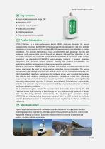
Key features ❖ Dual-axis measurement range ±90° ❖ Resolution 0.01° ❖ Dynamic accuracy ±0.1° ❖ Static accuracy ±0.05° ❖ CANOpen protocol ❖ Three protection levels available Product Introduction DTS6 CANOpen is a high-performance digital MEMS dual-axis dynamic tilt sensor independently developed by RUICOM Technology, specifically designed for real-time attitude monitoring of moving vehicles. It is optimized for tilt measurement under vibration or motion conditions. This product integrates a triaxial accelerometer and gyroscope sensing unit, achieving multi-source data fusion through an adaptive...
Open the catalog to page 2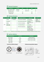
Electrical Parameters Connector pin definition diagram PCBA board wiring definition diagram
Open the catalog to page 4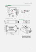
Product Size PCBA Size PCBA size: L39×W37×H12.2mm Installation size: L35×W28mm Suggested screw: 4 M2 screws Single-head (male) connector Shell Szie Shell Size: L83×W47×H22.5mm Installation Size: L64×W39×H6.5mm Shell material: aluminum alloy Suggested screws: 4 M4 screws
Open the catalog to page 5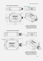
- www.ruicomtech.com Double-headed connector Shell Szie Shell Size: L96×W47×H22.5mm Installation Size: L64×W39×H6.5mm Shell material: aluminum alloy Suggested screws: 4 M4 screws Corrosion-resistant shell size diagram Shell Size: L95.3×W56×H24.5mm Installation Size: L64×W39×H6.5mm Shell material: 304 stainless steel Suggested screws: 4 M4 screws 6
Open the catalog to page 6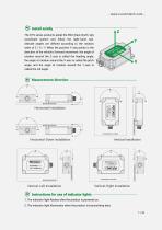
Install axially- The DTS series products adopt the ENU (East-North-Up) coordinate system and follow the right-hand rule. Attitude angles are defined according to the rotation order of Z / X / Y. When the positive Y-axis points in the direction of the vehicle's forward movement: the angle of rotation around the Z-axis is called the heading angle, the angle of rotation around the X-axis is called the pitch angle, and the angle of rotation around the Y-axis is called the roll angle. MOUNTING SURFACE MOUNTING SURFACE Installation surface Horizontal-Down Installation Vertical Installation TILT SENSOR...
Open the catalog to page 7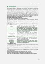
The DTS series CANopen is based on the DS410 standard, and CANopen is based on the Controller Area Network (CAN) developed in the automotive industry in the 1980s. The CANopen application protocol was introduced by the multi-vendor association CAN in Automation (CiA) to ensure full compatibility of industrial automation products. It is a multiplexed access system (up to 127 devices), meaning all devices can access the bus. These devices are components of the CANopen bus. Simply put, CANopen operates in a client-server model. Each device checks if the bus is idle; if idle, the device can send...
Open the catalog to page 8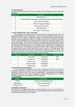
The general boot-up process of DTS series CANopen and the mapping of various modes are as follows: The DTS series is a highly flexible device, and all parameters can be set via the CAN bus. This chapter is divided into two main parts: an operational description of the DTS series and PDO/SDO programming for the DTS series.
Open the catalog to page 10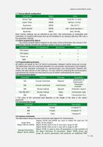
2.1 Factory default configuration
Open the catalog to page 11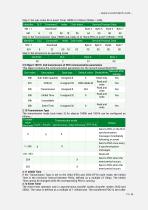
Step 2: Set sub-index 05 in Event Timer 1800h to 100ms (100dec = 64h); Service/Process Data Identifier DLC Command Index Sub-index NN = 1 Download Byte 4 Byte 5 Byte 6 Byte 7 Step 3: Set Transmission Type (1800h sub-index 2) to "Send PDO on event" (254dec = FEh) Service/Process Data Identifier DLC Command Index Sub-index Step 4: Set all sensors to operating mode If the Transmission Type is set to the 254d (FEh) and 255d (FFH) cycle mode, the Inhibit Time is the minimum interval between PDOs, defined as a multiple of 100ps. The Inhibit Time cannot be changed while the corresponding PDO is running....
Open the catalog to page 13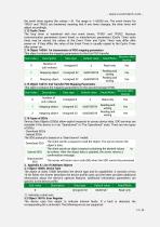
the event timer expires (for values > 0). The range is 1-65536 ms. The event timers for TPDO1 and TPDO2 are hardwired, meaning that if one timer changes, the other timer will adjust accordingly. The loop timer is hardwired with two event timers, TPDO1 and TPDO2. Because communication parameters (event timer) or manufacturer parameters (Cyclic Timer cycle time) may be stored, the values of the Event Timer and Cyclic Timer may differ after power-on. If they differ, the value of the Event Timer is usually copied to the Cyclic Timer after power-on. 2.15 Object 1A01H: 2nd Transfer PDO Mapping Parameters...
Open the catalog to page 14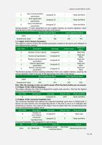
3.11 Object 1011H: Restore Parameters This object is used to restore the writable parameters related to the device and CANopen to their default factory settings.____
Open the catalog to page 16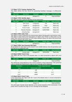
3.14 Object 1017h: Producer Heartbeat Time This object defines the time interval for generating heartbeat messages, in milliseconds (ms)._____ The valid range of preset values depends on the current resolution of the inclinometer. If the preset value is outside the range, an error message will be displayed.
Open the catalog to page 17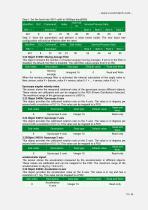
Step 1: Set the baud rate 3001 sub0 to 500kbps baud(05h) This object provides the acceleration value on the X-axis. The value is in mg and has a resolution of 1 mg. This value can be mapped to a PDO.__
Open the catalog to page 19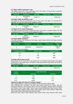
3.27 Object 3404H: Acceleration Y-axis This object provides the Y-axis acceleration value. This value is in mg and has a resolution of 1 mg. This value can be mapped to a PDO.___ Note: Changing the "resolution" will have side effects because the sensor uses the configured resolution, and rounding effects must be considered. Affected objects: Reading and writing: preset slope long16, preset slope lateral16,differential slope long16 offset, differential slope lateral16 offset, preset slope long32, preset slope lateral32, differential slope long32 offset, differential slope lateral32 offset; Read-only:...
Open the catalog to page 20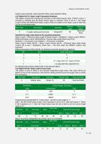
- www.ruicomtech.com -long32, slope lateral32, slope lateral32 offset, slope lateral32 offset„
Open the catalog to page 21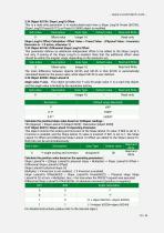
3.34 Object 6013H: Slope Long16 Offset This is a read-only parameter. It is recalculated each time a Slope Long16 Preset (6012H), Slope Long32 Preset (6112), or Preset X (2600) object is modified.__ For detailed instructions, please refer to the relevant object. Slope Lateral16 Offset(6023) = Slope Lateral16 Preset(6022) - Physical slope Slope Lateral16 (Y) at tacc * Multiplier), tacc = the time when the PRESET request was executed. Differential Slope Lateral! 6 Offset(6024): An absolute increment (positive or negative)._
Open the catalog to page 22All Shenzhen Ruicom Technology Co., Ltd. catalogs and technical brochures











- Display module
- Industrial display panel
- Color display panel
- Digital inclination sensor
- Triaxial acceleration sensor
- Built-in display
- 2-axis tilt sensor
- MEMS inclination sensor
- Multi-axis tilt sensor
- High-precision tiltmeter
- Analog inclination sensor
- IP67 inclination sensor
- Industrial accelerometer
- 1-axis tilt sensor
- MEMS accelerometer
- RS-485 display panel
- Accelerometer with built-in electronics
- Vibration sensor