
- Catalogs
- Shenzhen Ruicom Technology Co., Ltd.
- RUICOM DTS6 CAN2.0 Dynamic tilt angle sensor


- Company
- Products
- Catalogs
- News & Trends
- Exhibitions
RUICOM DTS6 CAN2.0 Dynamic tilt angle sensor

RUICOM DTS6 CAN2.0 Dynamic tilt angle sensor
- Measuring Range: Roll ±180°, Pitch ±90°, Yaw ±180°
- Dynamic Accuracy: ±0.1°
- Static Accuracy: ±0.05°
- CAN2.0A/B Protocols
- Three Protection Classes
The DTS CAN2.0 A/B is a high-precision digital dynamic tilt sensor by RUICOM Technology, utilizing advanced MEMS technology. It is designed for real-time attitude monitoring of moving vehicles, measuring roll, pitch, and azimuth angles, suitable for dynamic or high-vibration environments. It features a dual CAN bus architecture for enhanced compatibility and scalability.
- Multi-axis inertial measurement unit with a three-axis accelerometer and gyroscope, using an adaptive Kalman filter for real-time attitude calculation.
- Dynamic compensation technology for real-time correction of errors and interference, ensuring dynamic accuracy.
- Industrial-grade reliability with a wide operating temperature range and high resistance to shock, vibration, and interference.
Applications include equipment with strong impact vibration, engineering vehicle measurement and control, construction equipment leveling, agricultural machinery, aircraft attitude control, and ship monitoring.
- Measurement Range: Roll ±180°, Pitch ±90°, Azimuth ±180°
- Resolution: 0.01°
- Static Accuracy: ±0.05°
- Dynamic Accuracy: ±0.1°
- Gyroscope Range: ±300°/s
- Acceleration Range: ±4g / ±16g (optional)
- Operating Temperature: -40℃ to +85℃
- Protection Class: IP67 / IP68 / Anti-corrosion
- Power Supply Voltage: 9-36 V
- Operating Current: 40mA at 12V
- Operating Temperature: -40 to +85℃
Models are available with different housing, protocol, installation methods, and applications. Example: DTS6-C2-HOB-S indicates standard housing, CAN2.0A protocol, horizontal installation, shipboard application, and single connector.
Pin definitions include protective ground, positive and negative power supply, and CAN_H and CAN_L for communication.
The sensor uses the ENU coordinate system and follows the right-hand rule for defining attitude angles. Installation sizes and materials are specified for different connector types.
The CAN 2.0 protocol supports 2.0A (11-bit ID) or 2.0B (29-bit ID). Various settings can be configured, such as node number, CAN baud rate, automatic output cycle time, output frame type, and azimuth angle zeroing.
Data frames include angle, acceleration, and gyroscope frames. Each frame type is parsed based on specific byte configurations, with examples provided for conversion to readable values.
- X-axis: The gyroscope speed is calculated as 54.14°/s from the hexadecimal values 0x15 and 0x26, resulting in a combined value of 0x1526 (5414), which is divided by 100.
- Y-axis: The speed is -54.14°/s, derived from 0xEA and 0xDA, resulting in 0xEADA (-5414), divided by 100.
- Z-axis: The speed is 90.00°/s, calculated from 0x23 and 0x28, resulting in 0x2328 (9000), divided by 100.
- Single-frame angle output: Outputs one angle frame periodically. The default output mode with a specific message format.
- Double-frame angle plus table output: Outputs two frames consecutively and periodically, with a defined message format.
- Three-frame angle gyroscope plus table output: Outputs three frames consecutively and periodically, with a specified message format.
- Each mode has a unique CAN-ID message format, which includes bytes for XL, XH, YL, YH, ZL, ZH, Temp, and additional identifiers for frame sequencing.
- Website: www.ruicomtech.com
- Email: [email protected]
- Phone: 0755-23087719
- After-sales support: +86 183 0761 1639
- Address: Building 1, Lixin Lake Creative Park, 1 Furui Rd, Fuhai St, Bao'an, Shenzhen, China
Catalog excerpts

DTS CAN2.0A/B Dynamic tilt angle sensor Product Manual
Open the catalog to page 1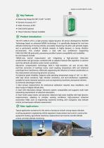
❖ Three Protection Classes Available The DTS CAN2.0 A/B is a high-precision digital dynamic tilt sensor developed by RUICOM Technology based on advanced MEMS technology. It is specifically designed for real-time attitude monitoring of moving vehicles, accurately measuring roll, pitch, and azimuth angles, and is particularly suitable for attitude analysis in highly dynamic or strong vibration environments. This product adopts a dual CAN bus architecture (supporting CAN2.0A/CAN2.0B protocols), possessing excellent system compatibility and scalability. Its core features include: 1) Multi-axis inertial...
Open the catalog to page 2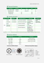
Electrical Parameters Connector pin definition diagram PCBA board wiring definition diagram
Open the catalog to page 4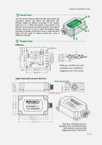
Install axial The DTS series products adopt the ENU (East-North-Up) coordinate system and follow the right-hand rule. Attitude angles are defined according to the rotation order of Z / X / Y. When the positive Y-axis points in the direction of the vehicle's forward movement: the angle of rotation around the Z-axis is called the heading angle, the angle of rotation around the X-axis is called the pitch angle, and the angle of rotation around the Y-axis is called the roll angle. Product Size PCBA Size PCBA size: L39×W37×H12.2mm Installation size: L35×W28mm Suggested screw: 4 M2 screws Single-head...
Open the catalog to page 5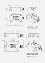
- www.ruicomtech.com Double-headed connector Shell Szie Shell Size: L96×W47×H22.5mm Installation Size: L64×W39×H6.5mm Shell material: aluminum alloy Suggested screws: 4 M4 screws Corrosion-resistant shell size diagram Shell Size: L95.3×W56×H24.5mm Installation Size: L64×W39×H6.5mm Shell material: 304 stainless steel Suggested screws: 4 M4 screws 6
Open the catalog to page 6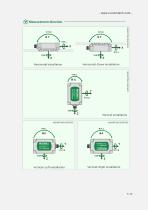
Measurement direction
Open the catalog to page 7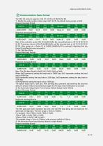
Communication frame format The CAN 2.0 protocol supports 2.0A (11 -bit ID) or 2.0B (29-bit ID). 1) Modify the node number (node range: 0x01 -0x7F), the default node number is 0x05 Request message format______ The fifth and sixth bytes represent the time, with the fifth byte being the low byte and the sixth byte the high byte. The time range is 10ms to 1000ms. The settable range is 10ms to 1000ms, with a factory default of 100ms. 4) Set the output frame type (factory default is angle frame) Request message format_______
Open the catalog to page 8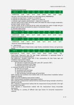
Response message format Data0-Data6: Represents data, the type (angle, acceleration, or gyroscope frame) is determined by the corresponding flag bit. flag (ddddccaa): Unsigned single byte, 8 bits, representing the data frame type and installation measurement method: aa: Indicates the data type of the frame 00: Indicates an angle frame (roll ±180°, pitch ±90°, azimuth ±180°); 10: Indicates gyroscope (±327.65°/s); cc: Indicates the power-on self-test result: 01: Acceleration self-test failed; 10: Gyroscope self-test failed; 11: Both acceleration and gyroscope self-tests failed; dddd: Indicates...
Open the catalog to page 9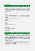
A: Angle data frame The CAN-ID is followed by eight bytes of data. The first two bytes, XL and XH, represent the X-axis acceleration magnitude. The third and fourth bytes, YL and YH, represent the Y-axis acceleration magnitude. The fifth and sixth bytes, ZL and ZH, represent the Z-axis acceleration magnitude. The acceleration magnitude is represented as an int16_t, with the low byte first and the high byte last. Dividing by 1000 yields the floating-point acceleration value. The seventh byte is reserved. Example of acceleration conversion: Flag = 0x01 indicates a horizontal installation measurement...
Open the catalog to page 10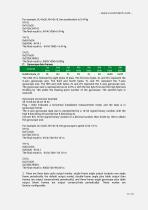
C: Gyroscope data frames____ The CAN-ID is followed by eight bytes of data. The first two bytes, XL and XH, represent the X-axis gyroscope size. The third and fourth bytes, YL and YH, represent the Y-axis gyroscope size. The fifth and sixth bytes, ZL and ZH, represent the Z-axis gyroscope size. The gyroscope size is represented as an inti 6_t, with the low byte first and the high byte last. Dividing by 100 yields the floating-point number of the gyroscope. The seventh byte is reserved. Gyroscope conversion example: Flag = 0x02 indicates a horizontal installation measurement mode, and the data...
Open the catalog to page 11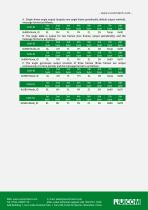
A. Single-frame angle output (outputs one angle frame periodically, default output method), message format as follows:: Web: www.ruicomtech.com E-mail: [email protected] Add:Building 1, Lixin Lake Creative Park, 1 Furui Rd, Fuhai St, Bao'an, Shenzhen, China
Open the catalog to page 12All Shenzhen Ruicom Technology Co., Ltd. catalogs and technical brochures
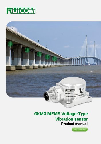





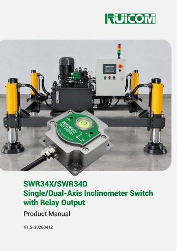
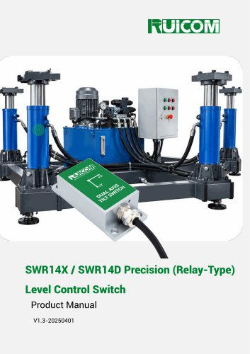
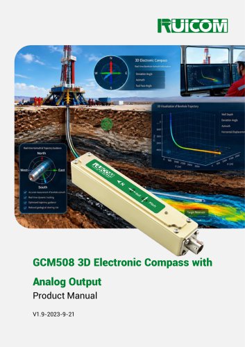






- Display module
- Industrial display panel
- Color display panel
- Tilt sensor
- Digital inclination sensor
- Triaxial acceleration sensor
- Built-in display
- 2-axis tilt sensor
- MEMS inclination sensor
- Multi-axis tilt sensor
- High-precision tiltmeter
- Analog inclination sensor
- IP67 inclination sensor
- Industrial accelerometer
- 1-axis tilt sensor
- MEMS accelerometer
- RS-485 display panel
- Accelerometer with built-in electronics
- Vibration sensor