
- Catalogs
- Shenzhen Ruicom Technology Co., Ltd.
- HTS6 High-Precision Digital Output Tilt Sensor

HTS6 High-Precision Digital Output Tilt Sensor

HTS6 High-Precision Digital Output Tilt Sensor
The HTS6 series are advanced tilt sensors designed for accurate roll and pitch angle measurements. They incorporate a 16-bit differential A/D converter and a 5th-order digital filtering algorithm, supporting multiple digital output protocols (RS485, RS232, RS422, TTL) for industrial communication. These sensors feature intelligent temperature drift compensation and are built for industrial-grade reliability, making them suitable for harsh environments.
The sensors are applicable in industrial automation, machinery platform leveling, photovoltaic tracking systems, aerospace attitude systems, and precision instrument leveling.
- Measuring range: ±1~±90° selectable
- Accuracy: 0.005° for small ranges
- Resolution: 0.001°
- Voltage input: DC 9~36V
- Output interfaces: RS485, RS232, RS422, TTL
The sensors offer a measurement range of ±10° to ±90°, with options for single or dual-axis. They have a resolution of 0.001° and varying accuracy based on the range. Designed for long-term stability, they have a protection class of IP67.
Operating voltage ranges from 9V to 36V, with an operating temperature range of -40 to +85°C.
Models can be customized based on axis, range, signal output, communication protocol, and installation direction.
The red indicator light shows power status and connection success or failure.
Pin definitions for TTL/RS232/RS485 and RS422 are provided, detailing power supply and data transmission lines.
The sensor measures L90×W59.1×H34mm and requires 3 M4 screws for installation.
The data frame format includes an identifier, data length, address code, command word, data field, and checksum. Various command words are used for angle reading, zero-point setting, communication rate setting, and output mode configuration.
The protocol requires a 10ms interval between data frames. Commands must be sent twice consecutively for settings to take effect. The protocol supports reading angle data and setting zero points, with detailed instructions for data frame format and conversion.
This document provides technical instructions for configuring and communicating with a sensor device. It includes command structures for setting various parameters such as sensor address, baud rate, and communication character format.
The register address 0010 controls the sensor output mode. A non-zero value (00FFH) sets the output to relative zero, while a zero value sets it to absolute zero. The last two bytes in the command are the CRC checksum.
Example command for reading data: Host sends 01H 03H 00H 02H 00H 05H 24H 09H, and the slave responds with the data and CRC checksum.
The default sensor address is 1. To change it, use the register address 0011. Commands must be sent twice consecutively. Example: Host sends 01H 06H 00H 11H 00H 04H D8H 0CH, and the slave confirms the change.
The default baud rate is 9600bps. Use register address 0012 to change it. Example: Host sends 01H 06H 00H 12H 00H A2H A8H 76H to set the baud rate to 19200bps. The command must be sent twice consecutively.
To read the sensor address, use the command with function code 42H. Example: Host sends 00H 42H 00H 11H 00H 01H E9H D1H, and the slave responds with the address and CRC checksum.
The default format is even parity. Use register address 0009 to change it. Example: Host sends 01H 06H 00H 09H 00H 01H 98H 08H to set the format to one start bit, 8 data bits, no parity, and one stop bit. This change takes effect after a power cycle.
For further assistance, contact Ruicomtech at [email protected] or visit their website at www.ruicomtech.com.
Catalog excerpts

HTS6 High-Precision Digital Output Tilt Sensor Product manual V1.9-20230918
Open the catalog to page 1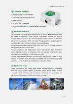
Technical Highlights ❖ Measuring range ±1~±90° selectable; ❖ Small measuring range accuracy 0.005°; ❖ Resolution 0.001°; ❖ DC 9~36V wide voltage input; ❖ RS485, RS232, RS422, and TTL output interfaces selectable. Product Introduction The HTS6 series high-performance single/dual-axis tilt sensors, while maintaining stable and reliable characteristics, further improve measurement accuracy and optimize temperature drift performance. This product integrates a high-precision 16-bit differential A/D converter, combined with a 5th-order digital filtering algorithm, to accurately measure the roll and...
Open the catalog to page 2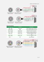
Male Connector Female Connector WEIPU SF1212P-5P WEIPU SF1210S-5P Male Connector Female Connector
Open the catalog to page 5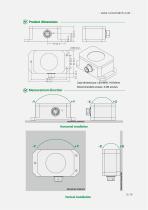
Product dimensions Measurement direction Recommended screws: 3 M4 screws
Open the catalog to page 6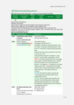
One. Data frame format: (8 data bits, 1 stop bit, no parity, default rate 9600) Data Format: Hexadecimal Identifier: Fixed at 68 Data Length: Length from the data length to the checksum (inclusive) Address Code: Address of the acquisition module, default is 00 The data field varies depending on the content and length of the command word. Checksum: The sum of the data length, address code, command word, and data field, without considering carry-over. Two. Command Word Parsing Simultaneous angle reading command Data Field (0 bytes) No Data Field Command Data Field (9 bytes) CC CD DD: 3 characters...
Open the catalog to page 7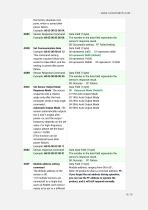
0X0C 0X8C Set Sensor Output Mode Response Mode: The sensor responds with a relative angle only after the host computer sends a read angle command; Automatic Output Mode: The sensor automatically outputs the X and Y angles after power-on, and the output frequency depends on the set value. For high-frequency output, please set the baud rate to 115200. (This function can be remembered even after power failure) Data Field (1 byte) The number in the data field represents the sensor's response result. 00: Success FF: Failure Data Field (1 byte) 00 Response Mode (Default) 01 5Hz Auto Output Mode 02...
Open the catalog to page 8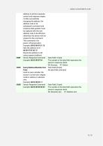
address to achieve separate control and response angles. 2) After successfully changing the address, the address code in all subsequent command and response data packets must be replaced with the new address code to be effective; otherwise, the sensor will not respond to the command. This command is for power-off preservation. Example: 68 05 00 0F 01 15 Sets the address to 01 68 05 FF 0F 00 13 Resets the address to 00 using a general address Sensor Response Command Example: 68 05 00 8F 94 Query Relative/Absolute Zero Point Used to query whether the sensor's current zero-degree mode is relative...
Open the catalog to page 9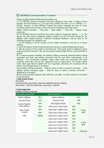
Please carefully read the following items before use: 1) The MODBUS protocol stipulates that there should be more than 3.5 bytes of time between two data frames (e.g., at a baud rate of 9600, this time is 3.5 x (1/9600) x 11 = 0. 004.). However, to leave sufficient margin, this sensor increases this time to 10ms. Therefore, please leave at least a 10ms time interval between each data frame. Master sends command ^ 10ms idle ^ Slave replies ^ 10ms idle ^ Master sends command... 2) The MODBUS protocol specifies the content related to broadcast address----0. This sensor can also receive broadcast...
Open the catalog to page 10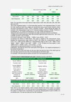
Note: 0010 is the register address, which controls whether the sensor output is a relative zero or an absolute zero. If it is non-zero (as in the example above, it is written with 00FFH), the output is a relative zero. Conversely, if it is zero (by changing bytes 5 and 6 to 00H), it is an absolute zero. The last two bytes are the CRC checksum.
Open the catalog to page 11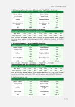
4. Set the sensor address (the sensor address is set to 1 by default at the factory).
Open the catalog to page 12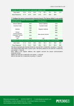
The above example sets the byte format to: one start bit + 8 data bits, no parity, + 1 stop bit. This setting takes effect after a power cycle. The factory default is one start bit + 8 data bits, even parity, + 1 stop bit. Note: 0009 is the register address; this register controls the sensor communication character format. 0000H: One start bit + 8 data bits, even parity, + 1 stop bit 0001H: One start bit + 8 data bits, no parity, + 1 stop bit Web:www.ruicomtech.com Tel:0755-23087719 E-mail:[email protected] Add:Building 1, Lixinhu Creative Park, No. 1 Furui Road, Qiaotou Community, Fuhai Subdistrict,...
Open the catalog to page 13All Shenzhen Ruicom Technology Co., Ltd. catalogs and technical brochures
 STSL Low-Power Tilt Sensor
21 Pages
 STS STANDARD OUTPUT TILT SENSOR
13 Pages
 HTS3D High-Precision Tilt Sensor
15 Pages
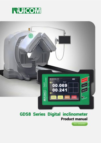 GDS8 Series Digital inclinometer
13 Pages

















- Display module
- Industrial display panel
- Color display panel
- Tilt sensor
- Digital inclination sensor
- Built-in display
- 2-axis tilt sensor
- MEMS inclination sensor
- Multi-axis tilt sensor
- Analog inclination sensor
- RS-485 display panel
- High-precision tiltmeter
- IP67 inclination sensor
- 1-axis tilt sensor
- Vibration sensor
- Rugged inclination sensor
- High-resolution inclinometer
- 2" display
- Angle measurement inclination sensor
- RS-485 inclinometer