
- Catalogs
- Shenzhen Ruicom Technology Co., Ltd.
- HTS3D High-Precision Tilt Sensor

HTS3D High-Precision Tilt Sensor
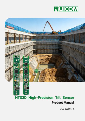
HTS3D High-Precision Tilt Sensor
The HTS3D is a high-precision biaxial tilt sensor by RUICOM Technology, designed for industrial applications like foundation pit monitoring and bridge inspection. It offers high accuracy, minimal temperature drift, and long-term stability within 0.01 degrees Celsius. The sensor uses a 5th-order filtering algorithm for roll and pitch angle calculations and features an RS485 interface with protection circuitry, supporting a wide voltage input range of DC 5~36V.
The sensor is suitable for applications such as foundation pit inclination measurement, railway monitoring, industrial automation, machinery platform leveling, photovoltaic tracking systems, aerospace attitude systems, and precision instrument leveling.
- Dual-axis tilt measurement with a range of ±85°
- Measurement accuracy of 0.01° and resolution of 0.001°
- Wide voltage input range of DC 5~36V
- Measurement Range: ±85°
- Resolution: 0.001°
- Measurement Accuracy: 0.01° at 25°C
- Long-Term Stability: 0.01°
- Zero-Point Temperature Coefficient: ±0.0002 °/°C
- Sensitivity Temperature Coefficient: ≤50 ppm/°C
- Response Bandwidth: 5 Hz
- Output Signal: RS485
- Shock Resistance: 100g@11ms
- Vibration Resistance: 10grms, 10–1000Hz
- Weight: ≤10g (excluding cables)
- Power Supply Voltage: 5-36 V
- Operating Current: 5 mA
- Operating Temperature: -40 to +85°C
- Storage Temperature: -40 to +85°C
Models are defined by communication protocol and installation orientation, e.g., HTS3D-77-H for 77 Protocol/Horizontal Installation.
Installation requires the sensor to be parallel to the target surface, minimizing dynamic and acceleration effects. The coordinate system is defined as Right-Front-Top (X-Y-Z).
77 Protocol: Uses a specific data frame format with commands for reading angles, setting zero points, and configuring baud rates.
MODBUS Protocol: Utilizes a standard format with commands for reading and writing data, including baud rate changes and address modifications.
- Data Reading: The module returns a 16-byte floating-point number with the high byte first. The address can be set to a general address (0xFA) to return the module's current address.
- Address Reading: The default address code is 1, and the module can return 2 bytes of integer data representing the address code (1-255).
- Address Modification: Commands can modify the module's address, requiring password authentication. Successful operations return the original instruction.
- Commands require password authentication in MBRTU mode. Successful authentication returns a specific command frame.
- Conditions: The device must be placed horizontally with tubes aligned straight.
- Commands: Include clearing, generating, and reading the GAMMA angle. Password authentication is required for these operations.
- The document details the CRC16 calculation method, including initializing a CRC register, XOR operations, and bit shifting.
Catalog excerpts
HTS3D High-Precision Tilt Sensor Product Manual V1.5-20260519
Open the catalog to page 1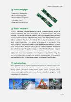
❖ Dual-axis tilt measurement; ❖ DC 5~36V wide voltage input. Product Introduction - The HTS3 is a biaxial tilt sensor launched by RUICOM Technology, primarily suitable for industrial engineering fields such as foundation pit tilt sensor monitoring and bridge inspection. This product inherits the stability of the HTS series while offering improved accuracy, superior temperature drift performance, and long-term stability controllable within 0.01 degrees Celsius. Through a built-in 5th-order filtering algorithm combined with biaxial gravity composite calculation, it can calculate the sensor's roll...
Open the catalog to page 2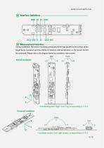
Interface Definition Measurement Direction During installation, the sensor mounting surface should be kept parallel to the surface of the target being measured, and the effects of dynamics and acceleration on the sensor should be minimized. Please refer to the diagram below for installation instructions: Vertical Installation *Coordinate system: Right-Front-Top, corresponding to X-Y-Z. Horizontal Installation * Coordinate system: front-right-bottom, corresponding to X-Y-Z. 5 / 15
Open the catalog to page 5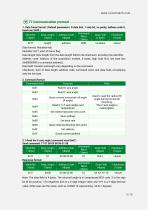
1. Data frame format: (Default parameters: 8 data bits, 1 stop bit, no parity, address code 0, baud rate 2400.)_____ Note: The data field is 4 bytes. The returned angle is in compressed BCD code. S is the sign bit (0 for positive, 1 for negative), XXX is a 3-digit integer value, and YYY is a 3-digit decimal value. Other axes are the same, such as 10268110 representing -26.811 degrees.
Open the catalog to page 6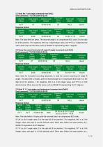
Response format: SX XX xx x0: X-angle value, S is the sign bit (0 for positive, 1 for negative), XXX is a 3-bit integer value, and xxx0 is a 3-bit decimal value. Other axes follow the same pattern, e.g., 00268110 represents 26.811 degrees. SY YY yy y0: Y-angle value, S is the sign bit (0 for positive, 1 for negative), YYY is a 3-bit integer value, and yyy0 is a 3-bit decimal value. Other axes follow the same pattern, e.g.,
Open the catalog to page 7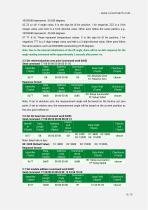
- www.ruicomtech.com -10255550 represents -25.555 degrees. SZ ZZ zz z0: Y-angle value, S is the sign bit (0 for positive, 1 for negative), ZZZ is a 3-bit integer value, and zzz0 is a 3-bit decimal value. Other axes follow the same pattern, e.g., 10255550 represents -25.555 degrees. ST TT tt t0: These represent temperature values. S is the sign bit (0 for positive, 1 for negative), TTT is a 3-digit integer value, and ttt0 is a 3-digit decimal value. Other axes follow the same pattern, such as 00233500 representing 23.35 degrees. Note: Due to the internal initialization of the tilt angle, there...
Open the catalog to page 8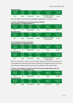
Response format:
Open the catalog to page 9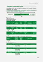
Communication format: 1 start bit, 8 data bits, no parity bit, 1 stop bit; Default parameters: Address code 1, baud rate 9600. The MODBUS protocol stipulates that there should be at least 3.5 bytes of time between two data frames, and this sensor extends this time to 15ms.
Open the catalog to page 10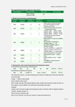
The requested data value is empty (no value exists): The instruction returns a 16-byte floating-point number; the high byte comes first, followed by the low byte. Length: 16 Return data length. Note: If Addr uses the 0xFA general address when sending the instruction, Addr will return to the module's current address. The instruction processing is the same. a.Read X and Y azimuth angles and temperature values. Function code 04. Register address: 16 bytes. Number of bytes: 16.
Open the catalog to page 11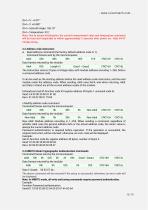
Note: Due to sensor initialization, the current measurement value and temperature command will be read and responded to within approximately 2 seconds after power-on.: Addr 84 0F 2.2 Address code instruction a. Read address command (the factory default address code is 1). Command frames sent by the microcomputer: The above command will be returned if the setup is successful; otherwise, an error code will be displayed. Note: In MBRTU mode, all write and tuning commands require password authentication.
Open the catalog to page 12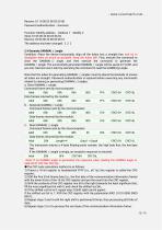
The address has been changed: [ 2 ] 2.4 Generate GAMMA( y ) angle Condition: Place the device horizontally, align all the tubes into a straight line, and try to straighten them as much as possible. Keep the tubes still. First, execute the command to clear the GAMMA(y) angle, and then execute the command to generate the GAMMA( y )angle. The successfully generated GAMMA( y ) angle will be saved in FLASH, and you can read and use it later by executing the command to read the GAMMA(y) angle. Note that the tubes for generating GAMMA(y) angles must be placed horizontally to ensure all tubes are straight....
Open the catalog to page 13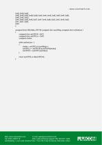
unsigned short MB_Make_CRC16( unsigned char *puchMsg, unsigned short usDataLen) { unsigned char uchCRCHi = 0xFF; unsigned char uchCRCLo = 0xFF; unsigned uIndex; while (usDataLen--) uIndex = uchCRCLoA*puchMsg++; uchCRCLo = uchCRCHiAauchCRCHi[uIndexj; uchCRCHi = auchCRCLo[uIndex]; Web: www.ruicomtech.com E-mail: [email protected] — ■ - - --y- Add:Building 1, Lixin Lake Creative Park, 1 Furui Rd, Fuhai St, Bao'an, Shenzhen, China m ^ k ^ ^ 11
Open the catalog to page 15All Shenzhen Ruicom Technology Co., Ltd. catalogs and technical brochures
 STSL Low-Power Tilt Sensor
21 Pages
 STS STANDARD OUTPUT TILT SENSOR
13 Pages
 GDS8 Series Digital inclinometer
13 Pages


















- Display module
- Industrial display panel
- Color display panel
- Tilt sensor
- Digital inclination sensor
- Built-in display
- 2-axis tilt sensor
- MEMS inclination sensor
- Multi-axis tilt sensor
- Analog inclination sensor
- RS-485 display panel
- High-precision tiltmeter
- IP67 inclination sensor
- 1-axis tilt sensor
- Vibration sensor
- Rugged inclination sensor
- High-resolution inclinometer
- 2" display
- Angle measurement inclination sensor
- RS-485 inclinometer