
- Catalogs
- Shenzhen Ruicom Technology Co., Ltd.
- GKP3 Low Frequency Vibration Sensor

GKP3 Low Frequency Vibration Sensor

GKP3 Low Frequency Vibration Sensor
The GKP3 is a triaxial vibration sensor designed for precise low-frequency vibration monitoring. It operates in the 0Hz or 0.1–100Hz frequency bands and supports the MODBUS protocol. The sensor is easy to install, resistant to electromagnetic interference, and suitable for applications such as satellite communication systems and radar antenna vehicles.
- Monitoring low-frequency vibrations in building structures
- Measuring vibrations in large rotating equipment
- Detecting minor vibrations in isolation platforms
- Measuring ultra-low frequency amplitudes in flexible structures
- Triaxial MEMS sensor
- Resolution: 1µg
- Measurement range: ±2g
- Output options: RS485, RS232, TTL
- IP67 protection rating
The sensor offers a measurement range of ±2g, a resolution of 1µg, and a bandwidth of 0.1~100 Hz. It supports various output rates and interfaces, with a power consumption of less than 16mA at 12 VDC.
The sensor should be installed parallel to the target surface to minimize errors. It uses a 2-meter PVC shielded wire and an M12*1.0 male 5-core connector. Proper grounding and terminating resistors are recommended for stable communication.
The GKP3 supports serial communication and MODBUS RTU protocols. Default settings include a baud rate of 9600, no parity for serial communication, and even parity for MODBUS. The protocol allows for reading and writing data, with specific commands for setting parameters and modes.
Data frames for both serial and MODBUS protocols include identifiers, data length, address codes, and checksums. The MODBUS protocol uses a CRC16 checksum and requires a minimum idle time between frames.
Ensure the sensor is mounted on a flat, stable surface and aligned parallel to the measurement axis to avoid errors. Incorrect installation can lead to measurement inaccuracies.
Models are available with different signal outputs and communication protocols, such as RS232 with serial communication or RS485 with MODBUS.
- Set all tilt sensors to a specific address or zero point (relative/absolute).
- Commands must be sent twice consecutively for effectiveness, with no other data frames in between.
- Use Modbus Function Code 03H to read sensor data.
- Data includes sensor address, function code, access register start address, and data length.
- Default sensor address is 1; use Function Code 06H to change it.
- Commands must be sent twice consecutively.
- Factory default baud rate is 9600bps; can be set to various rates (4800 to 230400bps).
- Commands must be sent twice consecutively.
- Default is even parity; can be set to no parity or odd parity.
- Changes take effect after a power cycle.
- Factory default is 0Hz; can be set to various frequencies (1Hz to 100Hz).
- Automatic output is only available when one product is connected to the 485 bus.
- Set automatic output data items using Function Code 06H.
- Example provided for setting all data outputs.
- Use Function Code 06H to set relative or absolute zero points.
- Non-zero value represents a relative zero; zero value represents an absolute zero.
Catalog excerpts

GKP3 Low Frequency Vibration Sensor Product Manual
Open the catalog to page 1
[Vj Technical Highlights ❖ Triaxial MEMS vibration sensor; The GKP3 is a triaxial vibration sensor independently developed for low-frequency vibration monitoring, featuring high precision and low noise. Each product undergoes calibration and compensation across the entire temperature range and approximately 336 hours of long-term stability testing before leaving the factory, ensuring stable performance under diverse operating conditions and continuous testing cycles. The sensor supports static vibration measurement in the 0Hz or 0.1-100Hz frequency bands and integrates two output protocols, including...
Open the catalog to page 2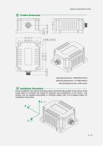
Product Dimensions Housing dimensions: L93×W70×H41mm Mounting dimensions: L71×W56×H8mm Recommended screws: 4 M6 screws Installation Orientation During installation, the sensor mounting surface should be kept parallel to the surface of the target object to minimize the impact of dynamics and acceleration on the sensor. This product can be installed horizontally or vertically; please refer to the diagram below for installation instructions:
Open the catalog to page 4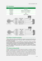
Male connector Signal ground Male connector Signal ground Interface connection instructions- 1. Select cables that conform to RS-485/RS-232 standards, ensuring the cable quality and performance meet the requirements. Twisted-pair cable is recommended due to its better anti-interference capability. 2. At both terminal devices in the RS-485/RS-232 communication network, terminating resistors (typically 120 ohms) need to be connected to eliminate signal reflections. Avoid connecting terminating resistors on intermediate devices to prevent signal interference. 3. To ensure system stability and security,...
Open the catalog to page 5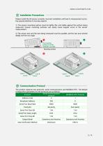
Please install the tilt sensor correctly. Incorrect installation will lead to measurement errors. Pay special attention to two key aspects: 1) The sensor mounting surface must be tightly, flat, and stable against the surface being measured. Uneven mounting surfaces can easily cause angular errors in the sensor measurement. 2) The sensor axis and the axis being measured must be parallel, and the two axes should ideally not form an angle. Mounting surface [vf Communication Protocol The product supports two protocols: serial communication and MODBUS RTU. The default configuration parameters for...
Open the catalog to page 6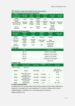
Default output data field format description Serial communication protocol format description The data field format uses big-endian mode, which is parsed as a data value multiplied by a coefficient. For example, the X-axis acceleration FF FF 4C 58 is -45992, and the result is -45992*0.000001 =-0.045992g. The Y-axis acceleration 00 01 86 A0 is 100000*0.000001=0.1g.
Open the catalog to page 7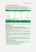
This output item is related to the automatic output mode command. The corresponding bit position determines the output, with lower bits indicating earlier data content. The automatic output item is 07F7H, meaning all content is output in the following order from left to right: Reservation Count | Status | Acceleration | Temperature.____ [vf Serial communication protocol l/Data Frame Format: Default communication parameters: Address 0, Baud rate 9600, 1 start bit, 8 data bits, no Valid address range: 0~254 Data length: Length from data length to checksum (including checksum); Data field: Varies...
Open the catalog to page 8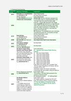
2. Command word parsing
Open the catalog to page 9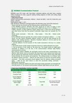
MODBUS uses RTU mode, with 'big-Endian' indicating address and data items, employs CRC16 checksum for data, supports reading holding registers at 0x03, and writing single registers at 0x06. 1. Data Frame Format: Default communication parameters: Address 1, Baud rate 9600, 1 start bit, 8 data bits, even parity, 1 stop bit; Valid address range: 1~247; CRC checksum: Checksum of all bytes before the CRC field, using 16-bit CRC checksum. Please note that you should read the following items carefully before use: l>The MODBUS protocol stipulates that there should be at least 3.5 bytes of time between...
Open the catalog to page 11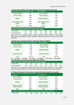
3. Set the sensor address: (The sensor address is set to 1 by default at the factory)
Open the catalog to page 12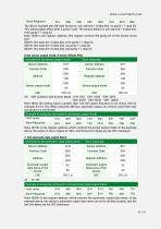
Note: 0020H is the register address, which controls the automatic output data items. In the example above, the sensor's automatic output data items are set to all data outputs, and the last two bytes are the CRC checksum.
Open the catalog to page 13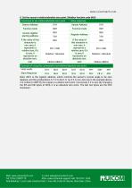
8. Set the sensor's relative/absolute zero point: (Modbus function code 06H) Note: 0010 is the register address, which controls the sensor's current angle to be zero degrees, and the accelerations X, Y, Z to be 0, 0,1g. If it is non-zero (as in the example above, it is written to 00FFH), the output is a relative zero point. Conversely, if it is zero (by changing the 5th and 6th bytes to 00H), it is an absolute zero point. The last two bytes are the CRC checksum. Web: www.ruicomtech.com E-mail: [email protected] — ■ - - --y- Add:Building 1, Lixin Lake Creative Park, 1 Furui Rd, Fuhai St, Bao'an,...
Open the catalog to page 14All Shenzhen Ruicom Technology Co., Ltd. catalogs and technical brochures
 STSL Low-Power Tilt Sensor
21 Pages
 STS STANDARD OUTPUT TILT SENSOR
13 Pages
 HTS3D High-Precision Tilt Sensor
15 Pages
 GDS8 Series Digital inclinometer
13 Pages


















- Display module
- Industrial display panel
- Color display panel
- Tilt sensor
- Digital inclination sensor
- Built-in display
- 2-axis tilt sensor
- MEMS inclination sensor
- Multi-axis tilt sensor
- Analog inclination sensor
- RS-485 display panel
- High-precision tiltmeter
- IP67 inclination sensor
- 1-axis tilt sensor
- Rugged inclination sensor
- High-resolution inclinometer
- 2" display
- Angle measurement inclination sensor
- RS-485 inclinometer