
- Catalogs
- Shenzhen Ruicom Technology Co., Ltd.
- GKG3 MEMS Digital Vibration sensor

GKG3 MEMS Digital Vibration sensor
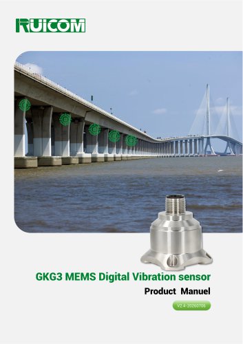
GKG3 MEMS Digital Vibration sensor
The GKG3 triaxial vibration sensor by RUICOM Technology is designed for engineering applications like vibration detection and shock testing. It supports RS232, RS485, or TTL communication and features a configurable address code for networking multiple sensors. It includes a built-in FFT processing unit for direct output of vibration parameters and uses single-crystal silicon capacitive sensing technology for low power consumption and high stability.
Application Scope
The sensor is suitable for flight data recording, structural fatigue monitoring, bridge health monitoring, high-speed train operation monitoring, vehicle vibration testing, wind turbine monitoring, track vibration monitoring, and heavy equipment monitoring.
Technical Highlights
- Optional RS232/485/TTL signal output
- Vibration range: 10~2000Hz, 10g
- Shock resistance: 100g@11ms, triaxial
- High stability and environmental performance
Performance Parameters
The sensor offers measurement ranges from ±2g to ±40g with high precision and stability, supports multiple output rates and communication protocols, has an IP67 protection class, and is made from aerospace aluminum.
Vibration Parameter Index
Provides data on acceleration, velocity, amplitude, and frequency with a frequency resolution of 4 Hz.
Ordering and Selecting
Models vary by measurement range and signal output protocols. Installation methods include a magnetic adsorption base.
Communication Protocol
Supports serial communication and MODBUS RTU protocols with default settings of a 9600 baud rate, no parity, and a broadcast address of 255. Configurable for automatic or question-and-answer output modes.
Installation and Dimensions
Housing dimensions are L34.2×W34.5×H38.5mm, recommended installation with 4 M3 screws.
Data Frame Format
Includes specific command words for reading and setting parameters, with a checksum for data verification.
MODBUS Communication Protocol
Uses MODBUS RTU mode with CRC16 checksum and standard error codes, supporting reading and writing of registers.
Specifies a minimum 10ms idle time between data frames for proper communication. The sensor can receive broadcast address 0 but will not respond, allowing for address setting, zero-point calibration, and testing.
Command Reliability
Commands must be sent twice consecutively to be effective. After power-on, commands can only be set once unless the device is powered on again.
Data Frame Format
Default communication parameters include an address of 1, baud rate of 9600, and a 16-bit CRC checksum. Valid address range is 1 to 247.
Data Types and Register Address Table
Provides a table of register addresses with corresponding data content and types, including temperature, acceleration, vibration frequency, velocity, and amplitude for X, Y, and Z axes. Data parsing involves multiplying register data by a coefficient.
Example Commands
Examples for reading X-axis data, setting sensor addresses, baud rates, parity bits, output modes, and bandwidth, including host query command and expected slave response.
Setting Parameters
Details commands for setting sensor parameters such as address, baud rate, parity bit, output mode, and bandwidth, requiring specific register addresses and CRC checksums.
Automatic Data Output
Describes configuration and reading of automatic data output items, with command sequences and expected responses.
Contact Information
Provides contact details for technical support and sales, including a web address, email, and phone numbers.
Catalog excerpts

GKG3 MEMS Digital Vibration sensor Product Manuel V2.4-20260706
Open the catalog to page 1
Technical Highlights ❖ RS232/485/TTL signal output optional; ❖ Vibration: 10~2000Hz, 10g; ❖ Shock: 100g@11ms, triaxial (half-sine wave); ❖ High stability and strong environmental performance: shock resistant, vibration resistant, and wide temperature range. Product Introduction The GKG3 triaxial Vibration sensor is a widely used multi-axis Vibration sensor series product independently developed by RUICOM Technology, suitable for various engineering scenarios such as vibration detection and shock testing. This series supports digital interface output, with selectable RS232, RS485, or TTL communication...
Open the catalog to page 2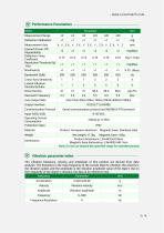
Vibration parameter index - The vibration frequency, velocity, and amplitude of this product are derived from data analysis. The frequency is the main frequency of the current object's vibration, the velocity is the vibration speed, and the amplitude is the vibration amplitude value of the object. Due to the irregularity of the object's vibration, the data is for reference only._
Open the catalog to page 3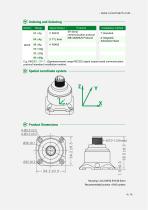
[vf Spatial coordinate system Product Dimensions
Open the catalog to page 4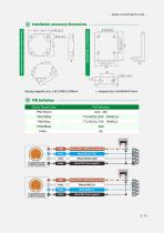
Strong magnetic [VT PIN Definition Stitch/Thread Color
Open the catalog to page 5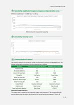
Sensitivity amplitude-frequency response characteristic curve [vf Sensitivity linearity curve SENSITIVITY LINEARITY GRAPH The product supports two protocols: serial communication protocol and MODBUS RTU. The default configuration parameters for the protocols are as follows: Automatic Output Data Items This output item is related to the automatic output mode command. The corresponding bit position determines the output; the lower the bit, the earlier the data appears. That is, all
Open the catalog to page 6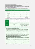
- www.ruicomtech.com -output content is ordered from left to right as: Acceleration|Frequency|Velocity|Amplitude|Temperature. For E.g: Serial communication protocol: Automatic output item is 1011H, then the automatic output data is: Acceleration|Frequency|Amplitude; Modbus protocol: Automatic output item is 9001H, then the automatic output data is: Acceleration|Amplitude|Temperature. The table below describes the relationship between output rate, data content, and baud rate. Please calculate and set the parameters appropriately based on the parameters. Automatic data output is invalid; only Automatic...
Open the catalog to page 7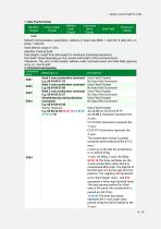
1. Data Frame Format: Default communication parameters: Address 0, baud rate 9600, 1 start bit, 8 data bits, no parity, 1 stop bit; Valid address range: 0~254; Data length: Length from data length to checksum (including checksum); Data field: Varies depending on the content and length of the command word; Checksum: The sum of data length, address code, command word, and data field, ignoring carry, i.e., Sum & 0xFF. 2. Command word parsing Read X-axis acceleration command Read Y-axis acceleration command Read Z-axis acceleration command Simultaneously read acceleration Sensor response Data Field...
Open the catalog to page 8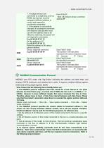
1. If multiple sensors are connected to a single bus, such as RS485, each sensor must be assigned a different address to control and respond to acceleration separately. 2. If the address is successfully changed, all subsequent command and response data packets must use the new address code to be effective; otherwise, the sensor will not respond to commands. Note: All products share a common address:FF Reset the address to 00 using a general address. Sensor response command Data Field (1 byte) E.g: 68 05 00 8F 00 94 The number in the data field represents the sensor response result: 00 Success...
Open the catalog to page 11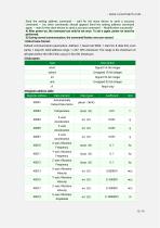
Send the setting address command -- wait for the slave device to send a success command -- (no other commands should appear) Send the setting address command again -- wait for the slave device to send a success command -- Modification successful Default communication parameters: Address 1, baud rate 9600, 1 start bit, 8 data bits, even parity, 1 stop bit; Valid address range: 1~247; CRC checksum: The range is the checksum of all bytes before the CRC field, using 16-bit CRC checksum.
Open the catalog to page 12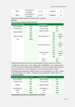
Commands must be sent twice consecutively to be effective.
Open the catalog to page 13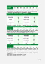
The above E.g sets the byte format to: one start bit + 8 data bits, no parity, + 1 stop bit. This setting takes effect after a power cycle. The factory default is one start bit + 8 data bits, even parity, + 1 stop bit. Note: 0009 is the register address; this register controls the sensor communication character format. 0000H: One start bit + 8 data bits, even parity, + 1 stop bit 0001H: One start bit + 8 data bits, no parity, + 1 stop bit
Open the catalog to page 14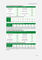
8. Set the sensor output mode: (Factory default: 0Hz) Note: 0000H is the register address, which controls the sensor's automatic data output. In the E.g above, the sensor's output is set to 9111H, and the last two bytes are the CRC checksum.
Open the catalog to page 15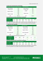
10. Read sensor output data items automatically: Note: 0014H is the register address, which controls the sensor bandwidth. In the E.g above, the sensor bandwidth is set to 500Hz, and the last two bytes are the CRC checksum. Web: www.ruicomtech.com E-mail: [email protected] — ■ - - ---Tel: 0755-23087719 After-sales technical support:+86 183 0761 1639 ■▼IIM Add:Building 1, Lixin Lake Creative Park, 1 Furui Rd, Fuhai St, Bao'an, Shenzhen, China m ^ k ^ ^ 11
Open the catalog to page 16All Shenzhen Ruicom Technology Co., Ltd. catalogs and technical brochures
 STSL Low-Power Tilt Sensor
21 Pages
 STS STANDARD OUTPUT TILT SENSOR
13 Pages
 HTS3D High-Precision Tilt Sensor
15 Pages
 GDS8 Series Digital inclinometer
13 Pages
















- Display module
- Industrial display panel
- Color display panel
- Tilt sensor
- Digital inclination sensor
- Built-in display
- 2-axis tilt sensor
- MEMS inclination sensor
- Multi-axis tilt sensor
- Analog inclination sensor
- RS-485 display panel
- High-precision tiltmeter
- IP67 inclination sensor
- 1-axis tilt sensor
- Rugged inclination sensor
- High-resolution inclinometer
- 2" display
- Angle measurement inclination sensor
- RS-485 inclinometer