
- Catalogs
- Shenzhen Ruicom Technology Co., Ltd.
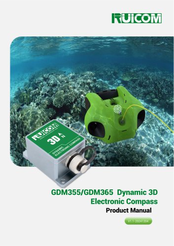
- GDM350 / GDM360 Dynamic 3D Electronic Compass

GDM350 / GDM360 Dynamic 3D Electronic Compass
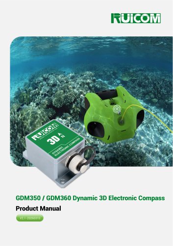
GDM350 / GDM360 Dynamic 3D Electronic Compass
The GDM350/360 is a high-performance 3D dynamic electronic compass featuring a 9-axis inertial measurement unit (IMU) that integrates a three-axis accelerometer, gyroscope, and magnetometer. It uses advanced dynamic inertial navigation algorithms to calculate pitch and roll angles in real-time, even under complex motion conditions. The compass employs intelligent calibration technology to suppress environmental magnetic interference, ensuring accurate geomagnetic azimuth measurements. It supports standard communication interfaces like RS232/RS485/TTL and is suitable for applications such as ship navigation and antenna stability control.
- Marine Navigation and Surveying
- GPS Integrated Navigation System
- Antenna Servo Control
- Infrared Imager Integration
- Laser Ranging Equipment Collaboration
- Map Completion System Support
- ROV Underwater Robot Navigation
- Marine Survey Instrument Support
- Tilt resolution: 0.1°
- Static tilt accuracy: 0.2°, dynamic accuracy: 0.5°
- DC 5V power supply
- Standard RS232/RS485/TTL output interface
- Hard and soft magnet, and tilt compensation
Key parameters include a heading accuracy of 0.8°, tilt accuracy of 0.2° static and 0.5° dynamic, and a gyroscope range of 500°/s. The device is designed to operate in temperatures ranging from -40℃ to +85℃ and withstands vibrations up to 2500g.
For optimal performance, the compass should be installed away from ferromagnetic materials and electromagnetic equipment. Copper screws and non-magnetic materials like aluminum alloy are recommended for mounting. On-site calibration and verification are advised to ensure measurement accuracy.
Calibration is necessary if compass accuracy is compromised or if there is fixed magnetic interference. The process involves rotating the device 360° to acquire spatial magnetic field data, followed by storing the calibration parameters.
The device uses a data frame format with an identifier, data length, address code, command word, and checksum. Various commands are available for reading angles, setting magnetic declination, starting calibration, and more. The protocol supports baud rates from 4800 to 115200.
The output includes attitude angles, 3-axis acceleration, and 3-axis gyroscope speed, with specific byte offsets and formats for each data type.
Catalog excerpts

GDM350 / GDM360 Dynamic 3D Electronic Compass Product Manual V2.1-20260310
Open the catalog to page 1
Technical Highlights ❖ Static tilt accuracy: 0.2°, dynamic accuracy: 0.5°; ❖ Standard RS232/RS485/TTL output interface; ❖ With hard magnet, soft magnet and tilt compensation. Product Introduction - The GDM350 / 360 is a high-performance 3D dynamic electronic compass with a built-in 9-axis inertial measurement unit (IMU), integrating a three-axis accelerometer, a three-axis gyroscope, and a three-axis magnetometer. By combining the high dynamic angle measurement capability of the gyroscope with the high stability attitude detection characteristics of the accelerometer, and using advanced dynamic...
Open the catalog to page 2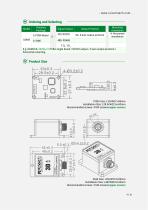
Ordering and Selecting Model Housing Package 5: PCBA Board Output Protocol 9A: 9 axis output protocol Mounting Orientation H:Horizontal - installation TTL: TTL E.g: GDM350-2329A-H: PCBA single board / RS232 output / 9 axis output protocol / horizontal mounting. Product Size PCBA Size: L33×W27×H9mm Installation Size: L28.5×W22.6×H2mm Recommended screws: 4 M3 screws(copper screws) Shell Size: L55×W37×H29mm Installation Size: L48×W28.6×H4mm Recommended screws: 3 M4 screws(copper screws)
Open the catalog to page 4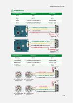
PIN/Thread Color
Open the catalog to page 5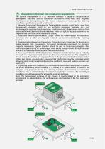
Measurement direction and installation requirements The azimuth measurement of a 3D electronic compass is based on the principle of geomagnetic induction, and its installation environment must meet strict magnetic interference control requirements. To ensure measurement accuracy, the following installation specifications should be followed: 1. Magnetic Environment Requirements: The installation location should be far away from ferromagnetic materials (such as iron products, permanent magnets, etc.) and electromagnetic equipment (such as motors, transformers, etc.); the minimum distance from potential...
Open the catalog to page 6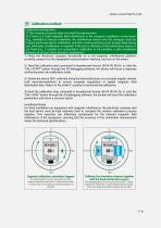
Calibration prerequisites: 1) The compass accuracy does not meet the requirements; 2) If there is a fixed magnetic field interference in the compass installation environment (e.g., installed on ferrous materials), the interference source and the compass must be rotated synchronously for calibration, and their relative positions must be kept fixed during use; otherwise, recalibration is required. If the size or distance of the interference source is not fixed (e.g., a variable iron component), calibration is not possible; a safe installation distance of at least 30cm should be maintained. 1) Place...
Open the catalog to page 7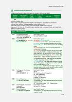
1 .Data frame format: (8 data bits, 1 stop bit, no parity, default rate 9600) Data Length: Length from the data length to the checksum (including the checksum); Address Code: Address of the acquisition module, default is 00; Data Field varies according to the content and length of the command word; Checksum: The sum of the data length, address code, command word, and data field, without considering carry. Descri Meaning/Example 0X04 Simultaneously read Data Field (0 bytes) Roll/Pitch/Heading angle No Data Field Command commands 68 04 00 04 08 0X84 Sensor Response Data Field (9 bytes) 10 05 01...
Open the catalog to page 8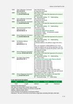
Protocol Item Descriptions: SOF: Start of Frame (SOF), a fixed value of 0x68; Length: Total number of bytes for all items except SOF; Load: Consists of commands or command content; Checksum: The sum of the first to third items, single byte, excluding the high-order byte.
Open the catalog to page 9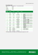
9-axis data type output Attitude angle + 3-axis acceleration + 3-axis gyroscope speed; *The heading angle is the magnetic north heading angle, ranging from 0 to 360°. Web:www.ruicomtech.com Tel:0755-23087719 E-mail:[email protected] Add:Building 1, Lixin Lake Creative Park, 1 Furui Rd, Fuhai St, Bao'an, Shenzhen, China
Open the catalog to page 10All Shenzhen Ruicom Technology Co., Ltd. catalogs and technical brochures
 STSL Low-Power Tilt Sensor
21 Pages
 STS STANDARD OUTPUT TILT SENSOR
13 Pages
 HTS3D High-Precision Tilt Sensor
15 Pages
 GDS8 Series Digital inclinometer
13 Pages










- Display module
- Industrial display panel
- Color display panel
- Tilt sensor
- Digital inclination sensor
- Built-in display
- 2-axis tilt sensor
- MEMS inclination sensor
- Multi-axis tilt sensor
- Analog inclination sensor
- RS-485 display panel
- High-precision tiltmeter
- IP67 inclination sensor
- 1-axis tilt sensor
- Vibration sensor
- Rugged inclination sensor
- High-resolution inclinometer
- 2" display
- Angle measurement inclination sensor
- RS-485 inclinometer