
- Catalogs
- Shenzhen Ruicom Technology Co., Ltd.
- GCM387 3D Electronic Compass Module

GCM387 3D Electronic Compass Module
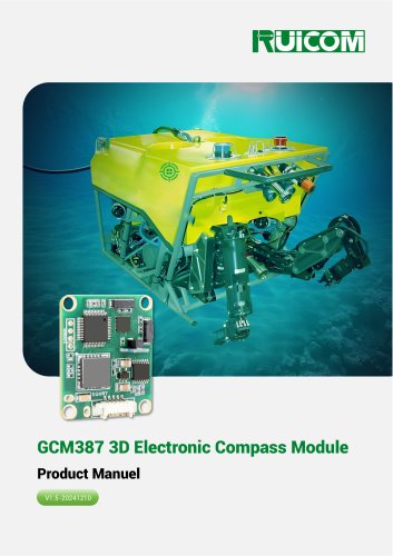
GCM387 3D Electronic Compass Module
Catalog excerpts

GCM387 3D Electronic Compass Module Product Manuel
Open the catalog to page 1
- www.ruicomtech.com -£vf Technical Highlights ❖ Roll angle measurement range: ±180°; ❖ Tilt accuracy: <0.2° (full range); ❖ Standard RS232/TTL output interface optional; ❖ With hard magnet, soft magnet and tilt compensation. Product Introduction- The GCM387 is a high-performance, cost-effective 3D electronic compass. It employs innovative 24-point rotating acquisition and calibration technology, effectively enhancing anti-interference capabilities while simplifying operation. An integrated high-precision accelerometer supports full-range (±180°) tilt compensation, ensuring accurate heading data...
Open the catalog to page 2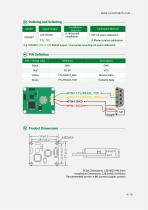
Ordering and Selecting Model Signal Output - Installation Direction H:Horizontal installation Calibration Method - MP: 24-point calibration R:Planar rotation calibration E.g: GCM387-232-H-MP: RS232 output / Horizontal mounting/24-point calibration. PIN Definition PIN / Thread color Receive Data Transmit Data Product Dimensions PCBA Dimensions: L33×W27×H9.5mm Installation Dimensions: L28.5×W22.6×H2mm Recommended screws: 4 M3 screws (copper screws)
Open the catalog to page 4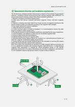
The 3D electronic compass azimuth measurement is based on the principle of geomagnetic induction. Installation requires an environment with minimal magnetic field interference. To ensure measurement accuracy, please follow these installation guidelines: 1. Magnetic Interference Protection Requirements: ❖ Keep away from ferrous materials, permanent magnets, motors, and other magnetic objects. ❖ Maintain a distance of at least 30cm from known sources of magnetic interference (the specific distance needs to be adjusted according to the magnetic field strength). ❖ Use copper fasteners for secure...
Open the catalog to page 5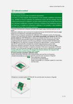
Calibration method Calibration prerequisites: 1) The compass accuracy does not meet the requirements; 2) If there is a fixed magnetic field interference in the compass installation environment (e.g., installed on ferrous materials), the interference source and the compass must be rotated synchronously for calibration, and their relative positions must be kept fixed during use; otherwise, recalibration is required. If the size or distance of the interference source is not fixed (e.g., a variable iron component), calibration is not possible; a safe installation distance of at least 30cm should...
Open the catalog to page 6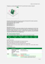
©Rotate at a constant speed of PITCH-450 for one full circle: As shown in Figure C During the rotation acquisition process, the compass will reply with the rotation acquisition and 24 points, the number of acquisition points, 24 point acquisition reply command: Calibration must acquire 24 points and complete the rotation simultaneously. One full circle horizontally, one full circle at +45° PITCH, one full circle at -45° PITCH, then click Stop. The electronic compass will pause for about 1 second while the internal CPU automatically calculates the sampled data and returns a set of data. Save calibration...
Open the catalog to page 7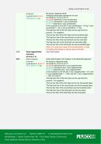
Read magnetometer command the sensor response result. Analyzing three bytes represents one axis. AA AB BB CC CD DD EE EF FF AA AB BB represents X-axis acceleration CC CD DD represents Y-axis acceleration EE EF FF represents Z-axis acceleration In the example on the left, X-axis acceleration = 0.01g, Y-axis acceleration = -0g, Z-axis acceleration = 1.02g The high four bits of the first byte are the sign bit (0 for positive, 1 for negative) The low four bits of the first byte are the hundreds digit The high four bits of the second byte are the tens digit The low four bits of the second byte are...
Open the catalog to page 10All Shenzhen Ruicom Technology Co., Ltd. catalogs and technical brochures
 STSL Low-Power Tilt Sensor
21 Pages
 STS STANDARD OUTPUT TILT SENSOR
13 Pages
 HTS3D High-Precision Tilt Sensor
15 Pages
 GDS8 Series Digital inclinometer
13 Pages










- Display module
- Industrial display panel
- Color display panel
- Tilt sensor
- Digital inclination sensor
- Built-in display
- 2-axis tilt sensor
- MEMS inclination sensor
- Multi-axis tilt sensor
- Analog inclination sensor
- RS-485 display panel
- High-precision tiltmeter
- IP67 inclination sensor
- 1-axis tilt sensor
- Vibration sensor
- Rugged inclination sensor
- High-resolution inclinometer
- 2" display
- Angle measurement inclination sensor
- RS-485 inclinometer