
- Catalogs
- Shenzhen Ruicom Technology Co., Ltd.
- GCM380/GCM385-N 3D Electronic Compass

GCM380/GCM385-N 3D Electronic Compass
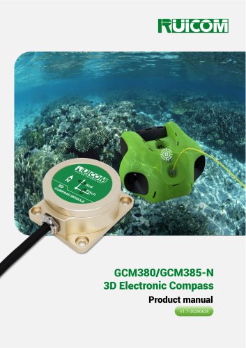
GCM380/GCM385-N 3D Electronic Compass
The GCM380/GCM385-N is a cost-effective 3D electronic compass with proprietary calibration technology for easy setup. It features a high-precision accelerometer for tilt compensation, providing stable heading data across a 360° roll range. It supports RS232, RS485, and TTL interfaces, making it suitable for integration into various systems. The device is compact, energy-efficient, and ideal for handheld devices and mobile platforms.
This compass is applicable in marine navigation, GPS systems, antenna control, infrared imaging, laser ranging, ROV navigation, and unmanned systems.
- Measurement range: Roll ±180°, Pitch ±85°
- Accuracy: Roll/Pitch 0.1°, Heading 0.5°
- Resolution: 0.1°
- Interfaces: RS232/RS485/TTL
- Compensation: Hard-iron, soft-iron, tilt
The device achieves optimal heading accuracy of 0.5° with a resolution of 0.1°. It supports hard-iron and soft-iron calibration and can handle magnetic interference. It operates within a temperature range of -40℃ to +85℃ and is IP67 rated.
Models are available as PCBA boards or with housing, supporting RS232, RS485, and TTL outputs. Installation can be horizontal or vertical.
Power and data connections are defined by color-coded wires for easy integration.
Installation should avoid magnetic interference, using non-magnetic materials like aluminum for mounting. Calibration and verification are recommended in the final application environment.
Calibration involves horizontal and vertical rotations, each requiring at least 20 seconds for validity. Commands are provided for initiating and saving calibration.
The data frame format includes identifiers, data length, address code, command code, and checksum. Commands cover reading angles, setting magnetic declination, calibration, and restoring factory settings.
Various automatic output modes are available, operating at frequencies of 5 Hz, 10 Hz, 25 Hz, and 50 Hz.
Commands such as 0X8C and 0XD0 are used to check the sensor's response. A data field value of 00 indicates success, while FF indicates failure.
The command 0X50 sets the geomagnetic detection threshold, with a value range from 1 to 10. The default factory setting is 4.
Commands like 0X2A and 0XAA are used to set and confirm the installation mode, either horizontal or vertical.
Commands 0X60 and 0X61 are used to read accelerometer and magnetometer data, respectively, with specific byte structures for each axis.
The module uses the NMEA 0183 protocol with a default baud rate of 19200. Data output rates can be set from 0 to 300 frames per minute using specific commands.
Commands are available to set the baud rate (4800, 9600, 19200) and configure the module for horizontal or vertical mounting. Settings are saved upon power-off.
Commands are provided for starting and saving azimuth calibration in horizontal and vertical orientations.
Catalog excerpts
GCM380/GCM385-N 3D Electronic Compass Product manual V1.7-20250628
Open the catalog to page 1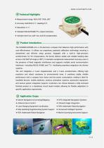
^Technical Highlights ❖ Measurement range: Roll ±180°, Pitch ±85°; ❖ Accuracy: Roll/Pitch 0.1°, Heading 0.5°; ❖ Standard RS232/RS485/TTL output interfaces; ❖ Includes hard-iron, soft-iron, and tilt compensation Product Introduction- The GCM380/GCM385-N is a 3D electronic compass that balances high performance with cost-effectiveness. It utilizes our proprietary, patented calibration technology, ensuring a streamlined and efficient setup process. Equipped with a built-in high-precision accelerometer for tilt compensation, the device delivers stable and reliable heading data across a full 360°roll...
Open the catalog to page 2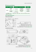
Ordering and Selection Model Housing Packaging 0: PCBA Board Signal Output SP: Serial communication protocol NMEA: NMEA Protocol Installation Orientation Output Protocol H: Horizontal installation V: Vertical installation TTL: TTL Level E.g: GCM380-232SP-H: PCBA board / RS232 output / Serial communication protocol / Horizontal mounting. Product Dimensions PCBA Dimension Diagram PCBA dimensions: L33 × W27 × H9.5 mm Mounting dimensions: L28.5 × W22.6 × H2 mm Recommended screws: 4 × M3 screws(copper screws) Housing Dimension Diagram Housing dimensions: L61.3 × W49 × H25.5 mm Mounting dimensions:...
Open the catalog to page 4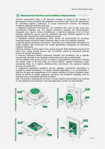
Azimuth measurement using a 3D electronic compass is based on the principle of geomagnetic sensing; therefore, the installation environment must meet strict requirements for controlling magnetic interference. To ensure measurement accuracy, the following installation guidelines should be observed: 1. Magnetic Environment Requirements: The installation site must be kept away from ferromagnetic materials (e.g., iron objects, permanent magnets) and electromagnetic equipment (e.g., electric motors, transformers). A minimum clearance of 40 cm from potential interference sources must be maintained...
Open the catalog to page 6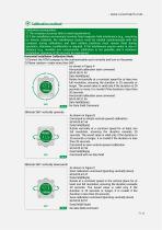
Calibration method Calibration prerequisites: 1) The compass accuracy fails to meet requirements; 2) If the installation environment involves fixed magnetic field interference (e.g., mounting on ferrous material), the interference source must be rotated synchronously with the compass during calibration, and their relative positions must remain fixed during operation; otherwise, recalibration is required. If the interference source varies in size or distance (e.g., movable iron components), calibration is not possible, and a minimum installation clearance of 30 cm must be maintained. Horizontal...
Open the catalog to page 7
- www.ruicomtech.com Vertical installation calibration mode: 1) Connect the communication port correctly using the HCM compass and turn on the power. 2) Planar rotation—more than 360°: As shown in Figure D Horizontal Calibration Start Command 68 04 00 41 45 Data field(0 byte) Rotate horizontally at a constant speed for at least one full revolution, ensuring the duration is 20 seconds or longer. The saved value is valid only if the duration is 20 seconds or more; it is invalid if the duration is less than 20 seconds. Horizontal Calibration Save Command 68 04 00 51 55 Data field(0byte) No data...
Open the catalog to page 8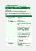
1. Data frame format: (8 data bits, 1 stop bit, no parity, default baud rate 9600) Data Length: Length from the Data Length field to the Checksum (inclusive); Address Code: Address of the data acquisition module; default is 00; Data Field: Content and length vary according to the Command Code; Checksum: Sum of Data Length, Address Code, Command Code, and Data Field (ignoring the carry). 2. Command Word Parsing Read Roll/Pitch/Heading Command with no data field 0X84 Sensor response Data field(10 byte) 10 05 01 04 01 00 1D AA AB BB:3 red bytes representing the Pitch axis CC CD DD:3 blue bytes representing...
Open the catalog to page 9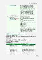
00 00 00 01 02 01 AA AB BB represents X-axis acceleration CC CD DD represents Y-axis acceleration EE EF FF represents Z-axis acceleration In the E.g: X-axis acceleration = 0.01g, Y-axis acceleration = -0g, Z-axis acceleration = 1.02g High 4 bits of the first byte: Sign bit Low 4 bits of the first byte: Hundreds digit High 4 bits of the second byte: Tens digit Low 4 bits of the second byte: Ones digit High 4 bits of the third byte: Tenths digit Low 4 bits of the third byte: Hundredths digit 0X61 Read magnetometer command Data field (0 bytes) 0XE1 Respond to magnetometer Three bytes represent one...
Open the catalog to page 12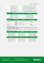
Web: www.ruicomtech.com E-mail: [email protected] — ■ - - --y- Add:Building 1, Lixin Lake Creative Park, 1 Furui Rd, Fuhai St, Bao'an, Shenzhen m ^ k ^ ^ 11
Open the catalog to page 13All Shenzhen Ruicom Technology Co., Ltd. catalogs and technical brochures
 STSL Low-Power Tilt Sensor
21 Pages
 STS STANDARD OUTPUT TILT SENSOR
13 Pages
 HTS3D High-Precision Tilt Sensor
15 Pages
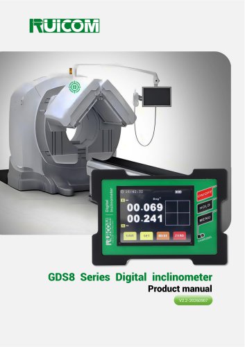 GDS8 Series Digital inclinometer
13 Pages




- Display module
- Industrial display panel
- Color display panel
- Tilt sensor
- Digital inclination sensor
- Built-in display
- 2-axis tilt sensor
- MEMS inclination sensor
- Multi-axis tilt sensor
- Analog inclination sensor
- RS-485 display panel
- High-precision tiltmeter
- IP67 inclination sensor
- 1-axis tilt sensor
- Vibration sensor
- Rugged inclination sensor
- High-resolution inclinometer
- 2" display
- Angle measurement inclination sensor
- RS-485 inclinometer