
- Catalogs
- Shenzhen Ruicom Technology Co., Ltd.
- DTS DIGITAL OUTPUT DYNAMIC HIGH SEISMIC INCLINATION SENSOR

DTS DIGITAL OUTPUT DYNAMIC HIGH SEISMIC INCLINATION SENSOR

DTS DIGITAL OUTPUT DYNAMIC HIGH SEISMIC INCLINATION SENSOR
The DTS is a high-performance digital MEMS dynamic tilt sensor designed by RUICOM Technology for monitoring the attitude of moving vehicles. It accurately measures roll, pitch, and yaw angles even under vibration or motion, using a multi-axis MEMS IMU with a three-axis accelerometer and gyroscope. The sensor includes an adaptive Kalman filter for real-time high-precision data output and supports RS485, RS232, and TTL interfaces for easy integration. It features non-contact measurement, high-precision ADC, and gyroscope compensation to enhance accuracy in dynamic environments.
The sensor is applicable in construction equipment leveling, ship attitude monitoring, high-impact vibration equipment, aircraft attitude control, agricultural machinery, and engineering vehicle monitoring.
- Dynamic accuracy: ±0.1°
- Static accuracy: ±0.05°
- Interfaces: RS485/232/TTL
- Measuring range: Roll ±180°, Pitch ±90°, Yaw ±180°
- Measurement Range: Roll ±180°, Pitch ±90°, Azimuth ±180°
- Resolution: 0.01°
- Static Accuracy: ±0.05°
- Dynamic Accuracy: ±0.1°
- Gyroscope Range: ±300°/s
- Acceleration Range: ±4g / ±16g
- Power-on startup time: ≤3.5S
- Response time: 0.01S
- Protection class: IP67 / IP68(optional)
- Power supply voltage: 9-36 V
- Operating current: 40mA(12V)
- Operating temperature: -40 to +85 ℃
The DTS series uses the ENU coordinate system and follows the right-hand rule for defining attitude angles. It offers various installation orientations and protection levels.
PCBA dimensions: L39×W37×H12.2mm. Shell dimensions vary based on the model and application.
The indicator light flashes when powered on and illuminates during data transmission.
The sensor supports binary communication with a frame format including sync, start, address, command, length, data, CRC, and end fields. It operates in query and continuous output modes, with default settings for baud rate and output frequency.
Data types include attitude angles, triaxial angular velocities, and triaxial acceleration, output in a specified order based on output masks.
Commands include setting and getting output masks, continuous data output, and setting output modes. The sensor supports both query and continuous output modes, with adjustable output frequencies.
This document provides technical instructions for configuring and operating a sensor device using the Modbus communication protocol. It includes details on setting temperature readings, zero points, sensor addresses, baud rates, communication formats, and automatic output frequencies.
The temperature is encoded in specific bytes, with the tens digit in byte 13 and the units and tenths digits in byte 14. For example, a response of 03H or 06H indicates a temperature of 30.6℃.
The sensor's zero point can be set to relative or absolute using Modbus Function Code 06H. A non-zero value indicates a relative zero, while zero indicates an absolute zero. Commands must be sent twice consecutively.
The default sensor address is 1. It can be changed using a specific command sequence, with the new address confirmed by the slave response. Commands must be sent twice consecutively.
The sensor's baud rate can be set to various speeds (4800 to 115200 bps) using a command sequence. The default is 9600 bps. Commands must be sent twice consecutively.
A specific command allows reading the current sensor address, with the response providing the address in the data field.
The sensor's communication format can be configured to different parity settings. The default is even parity. Commands must be sent twice consecutively and take effect after power-on.
The sensor's output frequency can be set from 0Hz to 100Hz. The default is 0Hz. Commands must be sent twice consecutively.
A command is provided to reset the sensor's heading angle to zero, confirmed by the slave response.
For further assistance, contact Ruicom Technology via their website, phone, or email.
Catalog excerpts

DTS DIGITAL OUTPUT DYNAMIC HIGH SEISMIC INCLINATION SENSOR Product Manual V1.1-20260515
Open the catalog to page 1
Technical Characteristics ❖ Dynamic accuracy ±0.1°; DTS is a high-performance digital MEMS dynamic tilt sensor independently developed by RUICOM Technology. Designed specifically for attitude monitoring of moving vehicles, it can accurately measure three-dimensional attitude parameters such as roll, pitch, and yaw angles, and is particularly suitable for tilt detection under vibration or motion conditions. This sensor employs a multi-axis MEMS inertial measurement unit (IMU), integrating a three-axis accelerometer and gyroscope, and incorporates an adaptive Kalman filter algorithm to ensure real-time...
Open the catalog to page 2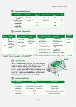
w Electrical Parameters Parameter Ordering Information Model Example: DTS6-232BIN-HOB-7: Standard enclosure / RS232 signal output / binary communication protocol / horizontal mounting / marine application / IP67 protection. Install axially The DTS series products adopt the ENU (East-North-Up) coordinate system and follow the right-hand rule. Attitude angles are defined according to the rotation order of Z / X / Y. When the positive Y-axis points in the direction of the vehicle's forward movement: the angle of rotation around the Z-axis is called the heading angle, the angle of rotation around...
Open the catalog to page 4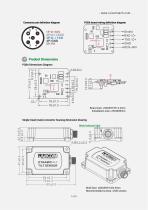
- www.ruicomtech.com Connector pin definition diagram PCBA board wiring definition diagram Product Dimensions PCBA Dimensions Diagram Board size: L39×W37×H12.2mm Installation size: L35×W28mm Single-head (male) connector housing dimension drawing Shell Size: L83×W47×H22.5mm Recommended screws: 4 M5 screws 5 /
Open the catalog to page 5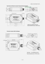
- www.ruicomtech.com head (male and female) connector housing dimension diagram Shell Size: L96×W47×H22.5mm Recommended screws: 4 M5 screws Corrosion-resistant shell size diagram Shell Size: L95.3×W56×H24.5mm Recommended screws: 4 M5 screws
Open the catalog to page 6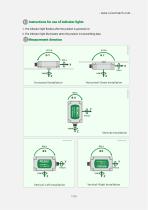
Instructions for use of indicator lights 1. The indicator light flashes after the product is powered on; 2. The indicator light illuminates when the product is transmitting data.
Open the catalog to page 7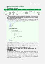
Binary communication frame format 1.0 Communication frame format A. LEN data length field includes the number of bytes in the data field, with the MSB first and the LSB last. A length of 0 indicates no data field. The longest data field length is 504 bytes, and the longest frame length is 512 bytes. B. CRC calculation starts from ADDR and includes CMD, the length field, and the data field, with the MSB first and the LSB last. The CRC is calculated using the following function: uint16 calcCRC(const uint8 *pBuffer, uint16 bufferSize) uint16 poly = 0x8408; uint16 crc = 0; uint8 carry; uint8 i_bits;...
Open the catalog to page 8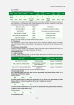
The response frame format is as follows: The sequence indicates the order in which the data is output. 3.2 Data output format 3.2.1 Attitude angles Roll, Pitch, and Yaw are represented using real32 (float), which is 12 bytes long and the unit is radians. Storage format: By using 'output masks(uint32)' to set the output data items and format, users can select the following data items for output.:_____ 3.2.2The angular rates of a three-axis gyroscope, Gx, Gy, and Gz, are represented by real32 (float), which is 12 bytes long and the unit is rad.s-1(radians per second). Storage format: 3.2.3The triaxial...
Open the catalog to page 9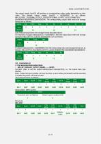
The output masks (uint32) will produce a corresponding output order depending on their value. The default output masks (uint32) = 0x00000007 is as follows: IMU_OUTPUT_EULER|IMU_OUTPUT_GYROSCOPES|IMU_OUTPUT_ACCELEROMETERS (0x00000001|0x00000002|0x00000004). The corresponding output data order and storage format are as follows:
Open the catalog to page 10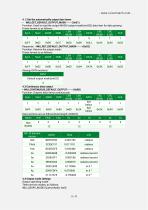
Function: Used to read the output MASK (output mask(uint32)) data item for data parsing. Frame format is as follows: 4.4 Output mode settings Output operating mode. There are two modes, as follows: IMU_QEURY_MODE (Query Mode): 0x00
Open the catalog to page 11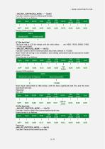
Function: Used to return the Mode and Divider; Frame format is as follows: Function: Returns the current baud rate;
Open the catalog to page 13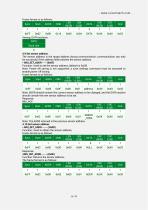
Frame format is as follows:
Open the catalog to page 14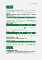
4.11 Set the measurement installation method(five installation methods: horizontal, horizontal downward, vertical upward, vertical left, and vertical right) Function: Used to set the sensor's installation method; (default is 0x00, horizontal orientation) Note: Power-off saving is not supported; a save settings command must be executed to enable this function. Frame format is as follows: Among: DATA sections The zero point of a sensor is divided into: absolute zero point and relative zero point. When set to absolute zero point, the reference plane for the sensor output tilt angle is the geographical...
Open the catalog to page 15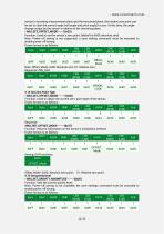
sensor's mounting measurement plane and the horizontal plane, the relative zero point can be set to clear the current angle (roll angle and pitch angle) to zero. At this time, the angle change output by the sensor is relative to the mounting plane. Function: Used to set the sensor's zero point; (default is 0x00, absolute zero) Note: Power-off saving is not supported; a save setting command must be executed to enable power-off saving. Frame format is as follows:
Open the catalog to page 16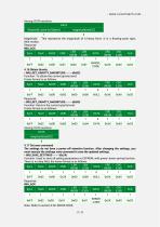
Among: DATA sections Note: Refer to section 6 for EEROR CODE;
Open the catalog to page 17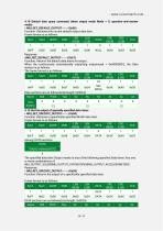
4.18 Default data query command (when output mode Mode = 0, question-and-answer mode) Function: Retrieves the current default output data item. Frame format is as follows:
Open the catalog to page 18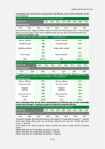
Commands must be sent twice consecutively to be effective, and no other commands can be sent in between. Example of using the command to set the sensor baud rate: Host sends Slave Response Note: 0012H is the register address, which controls the sensor baud rate. In the example above, the sensor baud rate is set to 19200, and the last two bytes are the CRC checksum. 6. Read sensor address code: Note: Commands must be sent twice consecutively to be effective, and no other commands can be sent in between. Powering on again will make the command effective. Example of setting sensor communication...
Open the catalog to page 22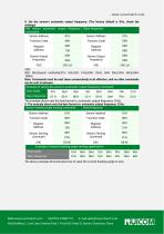
8. Set the sensor's automatic output frequency: (The factory default is 0Hz, check the settings)__ The above example demonstrates how to reset the current heading angle to zero. Web:www.ruicomtech.com Tel:0755-23087719 E-mail:[email protected] Add:Building 1, Lixin Lake Creative Park, 1 Furui Rd, Fuhai St, Bao'an, Shenzhen, China
Open the catalog to page 23All Shenzhen Ruicom Technology Co., Ltd. catalogs and technical brochures
 STSL Low-Power Tilt Sensor
21 Pages
 STS STANDARD OUTPUT TILT SENSOR
13 Pages
 HTS3D High-Precision Tilt Sensor
15 Pages
 GDS8 Series Digital inclinometer
13 Pages







- Display module
- Industrial display panel
- Color display panel
- Tilt sensor
- Digital inclination sensor
- Built-in display
- 2-axis tilt sensor
- MEMS inclination sensor
- Multi-axis tilt sensor
- Analog inclination sensor
- RS-485 display panel
- High-precision tiltmeter
- IP67 inclination sensor
- 1-axis tilt sensor
- Vibration sensor
- Rugged inclination sensor
- High-resolution inclinometer
- 2" display
- Angle measurement inclination sensor
- RS-485 inclinometer