
- Catalogs
- SHENZHEN RION TECHNOLOGY CO.,LTD
- Rion AKM392 Vibration Sensor


Rion AKM392 Vibration Sensor
1 /15Pages
Rion AKM392 Vibration Sensor
1 /15Pages
Catalog excerpts

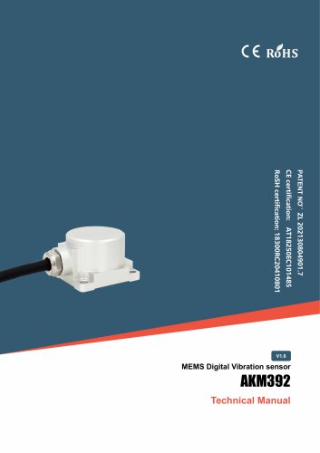
AKM392 MEMS Digital Vibration sensor MEMS Digital Vibration sensor
Open the catalog to page 1
AKM392 MEMS Digital Vibration sensor ○ CE certification: AT18250EC101485 ○ RoHS certification: 18300RC20410801 ○ China National Intellectual Property Appearance Patent (Patent No .: ZL 202130804901.7) ○ Revision time:2026-7-20 Note: Product functions, parameters, appearance, etc. will be adjusted as the technology upgrades. Please contact our pre-sales business to confirm when purchasing. Disclaimer This product is developed exclusively for commercial applications and is prohibited from being used for illegal purposes, such as military activities, research related to nuclear, chemical, or biological...
Open the catalog to page 2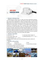
AKM392 three-axis vibration sensor is a widely used product independently developed , which can be applied to vibration testing, impact testing and other fields. The product adopts digital interface output, RS232/485/TTL is optional, and different address codes can be set. Multiple sensors are connected in series for a long distance, which is convenient for multi-point measurement and data analysis. The AKM392 is a monocrystalline silicon capacitive sensor consisting of a micromachined silicon chip, a low-power ASIC for signal conditioning, a microprocessor for storing compensation values, and...
Open the catalog to page 3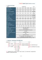
AKM392 MEMS Digital Vibration sensor ► PRODUCT ORDERING INFORMATION E.g: AKM392-02-T-68: indicates RS232 signal output/± 2g measurement range/standard installation mode/Rion68 protocol. 4/15
Open the catalog to page 4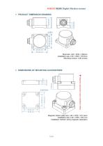
AKM392 MEMS Digital Vibration sensor ▶ PRODUCT DIMENSION DRAWING Shell size: L36 × W32 × H24mm Installation size: L29 × W25 × H5.5mm Mounting screws: 4 M4 screws ▶ DIMENSIONS OF MOUNTING ACCESSORIES Magnetic bottom plate size: L36 × W32 × H11.6mm Installation size: L29 × W25 × H8.1mm Installation method: strong magnetic adsorptio
Open the catalog to page 5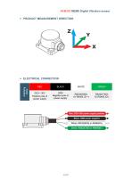
► ELECTRICAL CONNECTION Color Red: DC9~36V power supply positive Black: GND power negative
Open the catalog to page 6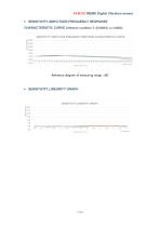
SENSITIVITY AMPLITUDE FREQUENCY RESPONSE CHARACTERISTIC CURVE Reference diagram of measuring range ±8G
Open the catalog to page 7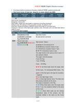
1, Data frame format: (8 data bits, 1stop bit, no check, default rate 9600) Data format: hexadecimal; Data length: length from data length to checksum (including checksum); Address code: the address of the acquisition module, the default is 00; Data field: change according to different content and length of command word; Checksum: The sum of the data length, address code, command word, and data field without regard to carry. 2. Command word analysis Desc. Meaning/Example Description 0X04 Simultaneous read Data field (0 byte) acceleration command No data domain command AAAB BB:three character...
Open the catalog to page 8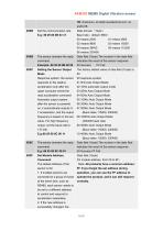
AKM392 MEMS Digital Vibration sensor 0X8B The sensor answers the reply command Example: 68 05 00 8B 00 90 Setting the Sensor Output Mode Response system: the sensor responds to the relative acceleration only after the upper computer sends the read acceleration command Automatic output system: after the sensor is powered on, it automatically outputs X, Y acceleration, and the output frequency is based on the set value. For high frequency output, set the baud rate to 115 200. The sensor answers the reply command The default address of the sensor is 00, 1. If multiple sensors are connected to a...
Open the catalog to page 9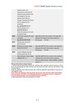
address code in all subsequent command and response data packets must be changed to the new address code after the change, otherwise the sensor will not respond to the command. 68 05 FF 0F 00 13 Reset the address to 00 with the general addr 0X8F The sensor answers the reply Data field (1 byte) The number in the data field command indicates the result of the sensor response 0XD3 Set Save Command Reply Data field (0BYTE) The number in the data field 68 05 00 D3 00 57 indicates the result of the sensor response 0XFF Version Software Number Directive 68 04 00 FF 03 Read Software Version Reply Data...
Open the catalog to page 10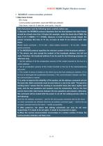
1. Data frame format: Communication parameters: baud rate 9600 bps (default) Data frame: 1start bit, 8 data bits, even parity, 1stop bit Note that please read the following items carefully before use: 1) Because the MODBUS protocol stipulates that the time between two data frames should be at least more than 3.5 bytes (for example, under the baud rate of 9600, the time is 3.5 x (1/9600) x 11 = 0.004s). However, in order to leave enough margin, the sensor increases this time to 10 ms, so leave at least 10 ms between each data frame. Master sends command -- 10 ms idle -- Slave replies command --...
Open the catalog to page 11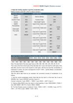
2. Read the holding register to get the acceleration data: Modbus function code 03H, which is output in format 1. Read the holding register to get the acceleration data Command Application Example 1: Host sends Slave replies Note: The data field of the slave reply frame is 50H, 46H, 00H, 00H, 23H, 20H, 00, 00, 00 The X axis is the first to third bytes of the data field, the Y axis is the fourth to sixth bytes of the data field, and the Z axis is the seventh to ninth bytes, with the low byte first. Acceleration is expressed in points, one point corresponds to 0.001°, 0.001 * (points-offset) is...
Open the catalog to page 12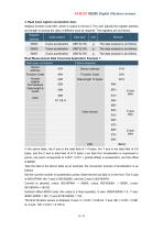
3. Read input register acceleration data: Modbus function code 04H, which is output in format 2. The user adjusts the register address and length to access the data of different axes as required. The registers are as follows: In the above table, the X axis is the data field of 1-4 bytes, the Y axis is the data field of 5-8 bytes, and the Z axis is data field of 9-12 bytes. Low byte first. Acceleration is expressed in points, one point corresponds to 0.001°, 0.001 * (points-offset) is acceleration, and the offset is 90000. Take the data in the above table as an example: the conversion process...
Open the catalog to page 13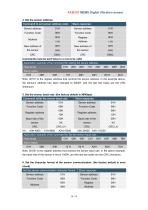
Application example of the command for setting the sensor address: Host sends
Open the catalog to page 14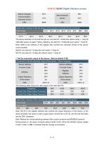
Slave replies Note: 0013H is the register address that controls the output frequency of the sensor. In the above example, the sensor is set to output data in format two at 25 HZ, and the last two bytes are the CRC checksum. Note: Method for mutual switching between Rion custom protocol and MODBUS protocol: During power-on, the upper computer always sends 0 xAA. When the Vibration sensor replies 0 XAA, 0 XAA, 0 XBB, it indicates that the change is successful.
Open the catalog to page 15All SHENZHEN RION TECHNOLOGY CO.,LTD catalogs and technical brochures
 RION HDA436T TILT SENSOR
14 Pages
 RION SMI815 SMI825
5 Pages
 RION DMI850 inclinometer
9 Pages
 RION WCA300A
3 Pages
 RION PSI-25M
1 Page
 Rion inclinometer SDA118T
10 Pages
 SDA116T/SDA126T
16 Pages
 RION SDA116T/SDA126T-CAN OPEN
11 Pages
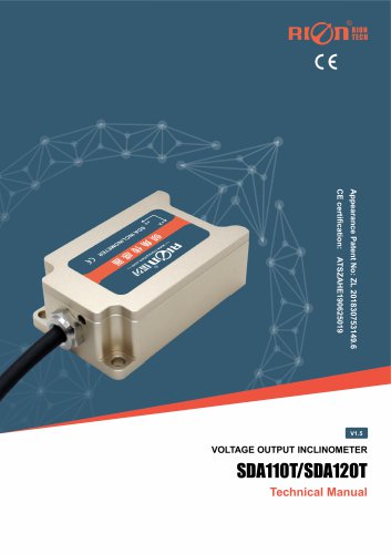 Rion SDA110T inclinometer
9 Pages
 Rion inclinometer SCA118T
10 Pages
 Rion inclinometer SCA116
16 Pages
 Rion inclinometer SCA110
10 Pages
 Rion inclinometer PCA826T
21 Pages
 Rion inclinometer MCA418T
2 Pages
 Rion inclinometer MCA416T
2 Pages
 Rion inclinometer MCA416LD
10 Pages
 Rion inclinometer MCA416L
10 Pages
 Rion inclinometer MCA416
2 Pages
 Rion inclinometer MCA410T
2 Pages
 Rion inclinometer MCA-85
12 Pages
 Rion inclinometer LCA318T
10 Pages
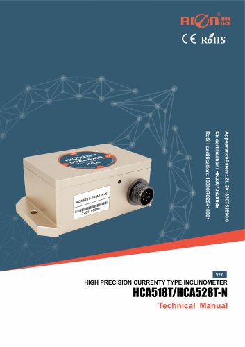 Rion HCA518T inclinometer
9 Pages
 Rion inclinometer HCA510T-N
11 Pages
 Rion inclinometer HCA510T
8 Pages
 Rion inclinometer HCA396B
11 Pages
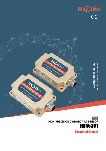 RION HDA536T INCLINOMETER
25 Pages
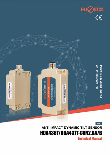 HDA437T/HDA437T-CAN2.0A/B
14 Pages
 HDA437T/HDA437
25 Pages
 HDA436T
25 Pages
 HDA436T-CANOpen
28 Pages
 ACA816T/ACA826T
17 Pages
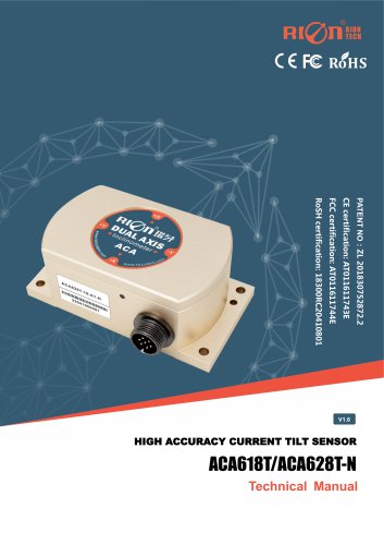 ACA618T/ACA628T-N
9 Pages
 Rion inclinometer ACA610T
9 Pages
 Rion electronic compass DDM350B
11 Pages
 Rion electronic compass DCM301B
11 Pages
 Rion electronic compass DCM250B
12 Pages
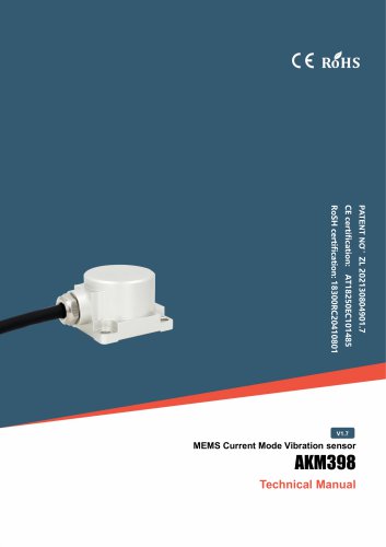 Rion AKM398 Vibration Sensor
6 Pages
 Rion AKM390 Vibration Sensor
6 Pages
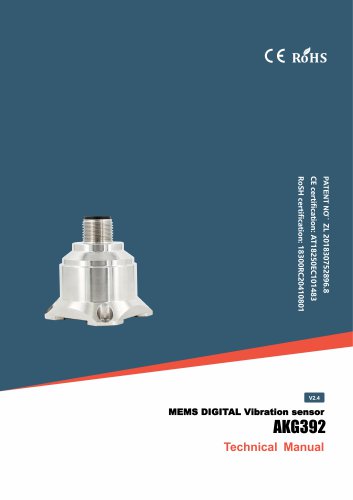 Rion Vibration Sensor AKG392
17 Pages
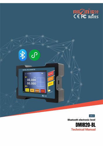




Archived catalogs
 SCA116T/SCA126T
9 Pages
- LCD screen
- Industrial monitor
- Panel-mount screen
- Pressure probe
- High-brightness monitor
- RION inclinometer
- TFT-LCD monitor
- Analog pressure sensor
- RION digital inclinometer
- Stainless steel pressure sensor
- Relative pressure sensor
- RION 2-axis inclinometer
- RION MEMS inclinometer
- RION multi-axis inclinometer
- Absolute pressure sensor
- RION analog inclinometer
- Gas pressure sensor
- Sensitive element pressure sensor
- RION high-precision inclinometer
- Liquid pressure sensor