- Catalogs
- SHENZHEN RION TECHNOLOGY CO.,LTD
- Rion inclinometer SCA116
- Company
- Products
- Catalogs
- News & Trends
- Exhibitions
Rion inclinometer SCA116
1 /16Pages

Rion inclinometer SCA116
1 /16Pages
Catalog excerpts

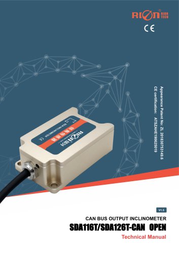
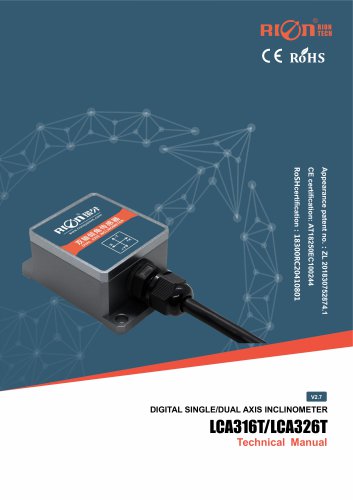
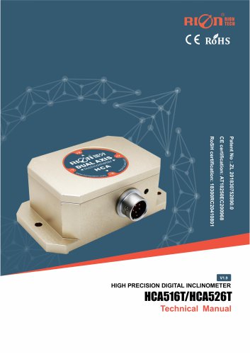
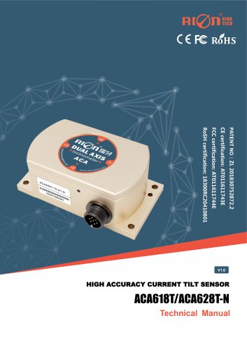
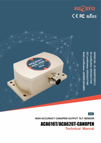
SCA116T/SCA126T MODBUS OUTPUT INCLINOMETER Appearance Patent No.:ZL 201830752892.X CE certification: AT011611741E FCC certification: AT011611742E RoSH certification: 18300RC20410801 MODBUS OUTPUT SINGLE/DUAL AXIS INCLINOMETER Technical Manual
Open the catalog to page 1
SCA116T/SCA126T MODBUS OUTPUT INCLINOMETER ○ CE certification number: AT011611741E ○ FCC certification number: AT011611742E ○ RoHS certification number: 18300RC20410801 ○ China National Intellectual Property Appearance Patent (Patent No.: ZL 201830752892.X) ○ Revision time:2024-08-07 Note: Product functions, parameters, appearance, etc. will be adjusted as the technology upgrades. Please contact our pre-sales business to confirm when purchasing. Disclaimer This product is developed exclusively for commercial applications and is prohibited from being used for illegal purposes, such as military...
Open the catalog to page 2
SCA116T/SCA126T MODBUS OUTPUT INCLINOMETER ▶ PRODUCTION SCA116T & SCA126T is the MODBUS output inclination sensor launched by RION Technology for industrial field control. It uses RS485 hardware differential bus to transmit data. Built-in high-precision 16bit A / D differential converter, through the 5th order filtering algorithm, can measure the tilt and pitch angle of the sensor output relative to the horizontal plane. built-in high-precision digital temperature sensorI, the temperature drift of the sensor can be corrected according to the change of the built-in temperature sensor to ensure...
Open the catalog to page 3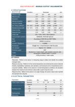
SCA116T/SCA126T MODBUS OUTPUT INCLINOMETER Measure range Measure axis Measure accuracy Long term.stability Zero Temp.coefficient Sensitivity temp-coeffi Response time Output rate communication protocol MODBUS / ROIN 68 Optional Insulation Resistance 100g@11ms / 3 Axial Direction (Half Sinusoid) Protection grade IP67 Standard as 1-meter length, wear-resistant, oil-proof, wide temperature, shielded cable 4 * 0.4mm2 ≤220g (including 1 meter cable) Cables Weight KEY WORDS Resolution : Refers to the sensor in measuring range to detect and identify the smallest changed value. Measure accuracy : Refers...
Open the catalog to page 4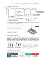
SCA116T/SCA126T MODBUS OUTPUT INCLINOMETER 1: Standara shell sealed Output Interface Measuring range Installation method Measuring axis Shell sealed 68: RION 68 Protocol MB: MODBUS Protocol 2: bared board,without shell E.g: SCA126T-10-232-MB: Standara shell sealed / Dual-axis / Horizontal / ±10° measure range / RS232 interface / MODBUS protocol. Note: The RS422 / TTL output interface is only for RION 68 protocol selection. ▶ MECHANICAL PARAMETERS ○ Connectors: 1m lead cable(customized) ○ Shell material: Aluminum Oxide ○ Installation: 4*M6 screws ▶ WORKING PRINCIPLE Adopt imported core control...
Open the catalog to page 5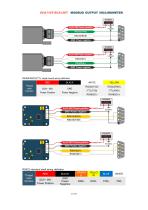
SCA116T/SCA126T MODBUS OUTPUT INCLINOMETER RS485/RS232/TTL single board wiring definition Thread color function Power Positive Power Negative RS422 standard shell wiring definition Thread color function
Open the catalog to page 6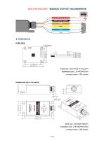
SCA116T/SCA126T MODBUS OUTPUT INCLINOMETER ▶ DIMENSION PCBA SIZE PCBA size: L46.5×W35.5×H12.5mm Installation size: L37×W29×H2mm ounting screws: 4 M3 screws DIMENSION WITH HOUSING Shell size: L90×W40×H26mm Installation size: L78×W29×H4.5mm ounting screws: 4 M6 screws
Open the catalog to page 7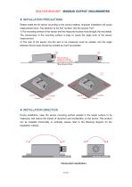
SCA116T/SCA126T MODBUS OUTPUT INCLINOMETER ▶ INSTALLATION PRECAUTIONS Please install the tilt sensor according to the correct method. Improper installation will cause measurement error. Pay attention to the first "surface" and the second "line": 1) The mounting surface of the sensor and the measured surface must be tight, flat and stable. The unevenness of the mounting surface is easy to cause the angle error of the sensor measurement. 2) The axis of the sensor and the axis to be measured must be parallel, and the angle between the two axes should be avoided as much as possible. ▶ INSTALLATION...
Open the catalog to page 8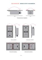
SCA116T/SCA126T MODBUS OUTPUT INCLINOMETER
Open the catalog to page 9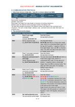
SCA116T/SCA126T MODBUS OUTPUT INCLINOMETER ▶ COMMUNICATION PROTOCOL 1. Data frame format: (8 data bits, 1 stop bit, no check, default rate 9600) Command Identifier Data length Address checksum word Data field (1byte) (1byte) code (1byte) (1byte) (1byte) 68 Data format: hexadecimal; Identifier: fixed at 68; Data length: the length from data length to checksum (including checksum); Address code: the address of the acquisition module, the default is 00; The data field changes according to the different content and length of the command word. Checksum: The sum of data length, address code, command...
Open the catalog to page 10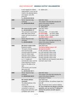
SCA116T/SCA126T MODBUS OUTPUT INCLINOMETER to zero degrees for relative measurement, or you can set it back to the absolute factory zero degree, save after power off E.g: 68 05 00 05 00 0A Sensor response reply command E.g: 68 05 00 85 00 8A Set communication speed E.g: 68 05 00 0B 03 13 This command is set to take effect after power off and restart, and save function at power off Sensor response reply command E.g: 68 05 00 8B 90 Set sensor output mode Response system: The upper computer needs to send read the angle command before the sensor reply the relative angle Automatic output system: After...
Open the catalog to page 11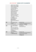
SCA116T/SCA126T MODBUS OUTPUT INCLINOMETER needs to be set to a different address to achieve separate control and response angles. 2.If the new address is successfully changed, the address code in all subsequent commands and response packets must be replaced with the new address code after the change to be effective, otherwise the sensor will not respond to the command. This command is a power-off save function. E.g: 68 05 00 0F 01 15 Set the address to 01. 68 05 FF 0F 00 13 Reset the general address FF to 00 Sensor response reply command E.g: 68 05 00 8F 94 Query relative/absolute zero Used...
Open the catalog to page 12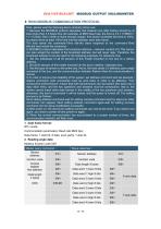
SCA116T/SCA126T MODBUS OUTPUT INCLINOMETER ▶ RION MODBUS COMMUNICATION PROTOCOL Note, please read the following items carefully before use: 1) Because the MODBUS protocol stipulates that between two data frames should be at least more than 3.5 bytes time (for example, at 9600 baud rate, the time is 3.5 × (1/9600) × 11 = 0.004s). But in order to leave enough margin, this sensor increases this time to 10ms, so please leave at least 10ms time interval between each data frame. The host sends the command-10ms idle-the slave responds to the command-10ms idle-the host sends the command ... 2) MODBUS...
Open the catalog to page 13All SHENZHEN RION TECHNOLOGY CO.,LTD catalogs and technical brochures
 Excavator 3D guidance system
7 Pages
 RION WCA300A
3 Pages
 RION PSI-25M
1 Page
 Rion inclinometer SDA118T
10 Pages
 SDA116T/SDA126T
16 Pages
 SDA116T/SDA126T-CAN OPEN
11 Pages
 Rion inclinometer SDA110T
9 Pages
 Rion inclinometer SCA118T
10 Pages
 SCA116T/SCA126T (2025)
11 Pages
 Rion inclinometer SCA110
10 Pages
 Rion inclinometer PCA826T
21 Pages
 Rion inclinometer MCA418T
2 Pages
 Rion inclinometer MCA416T
2 Pages
 Rion inclinometer MCA416LD
10 Pages
 Rion inclinometer MCA416L
10 Pages
 Rion inclinometer MCA416
2 Pages
 Rion inclinometer MCA410T
2 Pages
 Rion inclinometer MCA-85
12 Pages
 Rion inclinometer LCA318T
10 Pages
 LCA316T/LCA326T
16 Pages
 LCA316T/LCA326T-CAN OPEN
11 Pages
 Rion inclinometer HCA518T
9 Pages
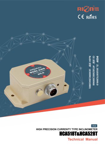 HCA518T&HCA528T
8 Pages
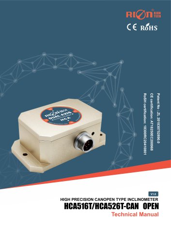 HCA516T/HACA526T-CAN
10 Pages
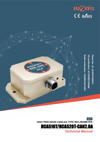 HCA516T/HACA526T-CAN2.0A
9 Pages
 HCA516T/HCA526T
16 Pages
 Rion inclinometer HCA510T-N
11 Pages
 Rion inclinometer HCA510T
8 Pages
 Rion inclinometer HCA396B
11 Pages
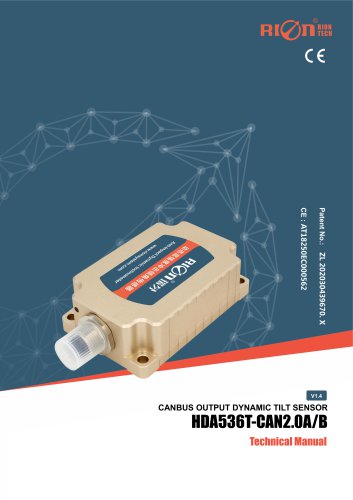 HDA536T-CAN2.0A/B
17 Pages
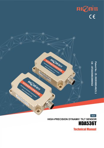 HDA536T
25 Pages
 HDA437T/HDA437T-CAN2.0A/B
14 Pages
 HDA437T/HDA437
25 Pages
 HDA436T
25 Pages
 HDA436T-CANOpen
28 Pages
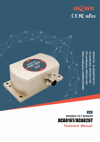 ACA816T/ACA826T
17 Pages
 ACA618T/ACA628T-N
9 Pages
 Rion inclinometer ACA610T
9 Pages
 Rion electronic compass DDM350B
11 Pages
 Rion electronic compass DCM301B
11 Pages
 Rion electronic compass DCM250B
12 Pages
 Rion acceleromwter RAM900S
39 Pages
 Rion acceleromwter RAM900
37 Pages
 Rion acceleromwter AKM398
6 Pages
 Rion acceleromwter AKM392
15 Pages
 Rion Vibration Sensor AKM390
6 Pages
 Rion acceleromwter AKG392
17 Pages


Archived catalogs
 SCA116T/SCA126T
9 Pages
- LCD screen
- Industrial monitor
- Panel-mount screen
- Red Rooster accelerometer
- Pressure probe
- High-brightness monitor
- TFT-LCD monitor
- Analog pressure sensor
- Single-axis accelerometer
- Red Rooster 3-axis accelerometer
- Red Rooster digital inclinometer
- Relative pressure sensor
- Stainless steel pressure sensor
- Compact accelerometer
- Red Rooster 2-axis inclinometer
- Red Rooster MEMS inclinometer
- General purpose accelerometer
- Red Rooster accelerometer with analog output
- Red Rooster multi-axis inclinometer