- Catalogs
- SHENZHEN RION TECHNOLOGY CO.,LTD
- Rion electronic compass DCM301B
- Company
- Products
- Catalogs
- News & Trends
- Exhibitions
Rion electronic compass DCM301B
1 /11Pages

Rion electronic compass DCM301B
1 /11Pages
Catalog excerpts

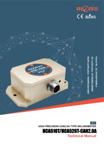
FCC certification: AT011611746E RoSH certification: 18300RC20410801 Technical Manual
Open the catalog to page 1
○ CE certification: AT011611745E ○ FCC certification: AT011611746E ○ RohS certification: 18300RC20410801 ○ China National Intellectual Property Appearance Patent Right (Patent No.:201730610577.9) ○ Revision date: 2024-08-08 ○ Product functions, parameters, appearance, etc. will be adjusted as technology upgrades. Please contact our pre-sales business to confirm when purchasing. Disclaimer This product is developed exclusively for commercial applications and is prohibited from being used for illegal purposes, such as military activities, research related to nuclear, chemical, or biological weapons,...
Open the catalog to page 2
▶ INTRODUCTION DCM301B/DCM302B is a 3D electronic compass with high precision using two-dimensional plane calibration algorithm. The calibration does not require a three-dimensional attitude tilt, and only needs to rotate the plane in place to complete the calibration process. Using hard magnetic and soft magnetic calibration algorithms, the compass can achieve ideal measurement results through three-dimensional calibration in an environment with magnetic interference. This compass integrates three-axis magnetic sensing technology, which can calculate the heading in real time through the central...
Open the catalog to page 3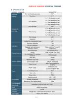
▶ SPECIFICATION DCM301B / DCM302B Compass heading The best heading accuracy Pitch accuracy Pitch tilt range Compass tilt parameter Roll accuracy Physical features Interface features Roll tilt range The best tilt compensation range Hard iron calibration Soft iron calibration Magnetic field interference calibration method Shell Dimension Yes Plane rotation in 1circle(2D Calibration) L60×W59×H33mm Weight RS-232/RS485/TTL interface connector Start delay Maximum output rate Communication rate 2400 to 19200baud Binary high performance protocol (Default)DC+5V Output format Power supply Power Environment...
Open the catalog to page 4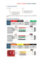
E.g.: DCM302B-232: Plane calibration 3D electronic compass(with enclosure sealed)/RS232 output ▶ ELECTRICAL CONNECTION WIRING DEFINITION FOR COMPASS WITH SHELL RED Color function PCBA WIRING DEFINITION ORANGE Color function
Open the catalog to page 5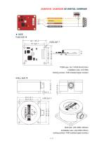
▶ SIZE PCBA SIZE ▼ PCBA size: L44.1×W35.55×H9.3mm Installation size: L37×W29 Ounting screws: 4 M3 screws(Copper screws) SHELL SIZE ▼ Shell size: L59×W60×H33mm Installation size: L49×W50×H5mm ounting screws: 4 M4 screws(Copper scre
Open the catalog to page 6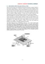
MEASURING DIRECTION AND INSTALLATION Since the azimuth angle of the DCM302B three-dimensional electronic compass is based on the principle of geomagnetism, it is important to choose an environmental installation location with minimal magnetic interference. Please install DCM302B as far away as possible from iron, magnets, motors, and other magnetic objects. Even if there are these magnetic media around, at least the distance needs to be controlled above 40CM (different magnetic fields interfere with the compass at different distances). To ensure that the product reaches the best measurement environment,...
Open the catalog to page 7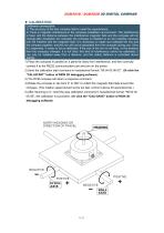
Calibration prerequisite: 1) The accuracy of the test compass fails to meet the requirements; 2) There is magnetic interference in the compass installation environment. This interference is fixed, and the distance between the interference magnetic field and the compass will not change after installation (for example: the compass is installed on an iron material, because iron will interfere with the magnetic field. It is necessary to rotate and calibrate the iron and the compass together, and the iron will not be separated from the compass during use. Once it is separated, it needs to be re-calibrated....
Open the catalog to page 8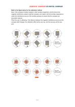
DCM301B / DCM302B 3D DIGITAL COMPASS Refer to the figure below for the calibration method Note: If the compass is fixedly installed in other ancillary equipment, and the device has magnetic interference, please install the compass, and rotate it with the ancillary equipment to collect the interference source of the ancillary products to ensure that the compass can accurately measure. When the user is calibrating, if the distance between the magnetic interference source and the compass itself changes, the calibration effect will be very low, and the accuracy will be very poor.
Open the catalog to page 9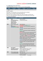
▶ COMMUNICATION PROTOCOL 1. Data frame format: (8 data bits, 1 stop bit, no parity, default rate 9600) Identifier Date Length Addr code Cmd word Date domain (1byte) (1byte) (1byte) (1byte) 68h Identifier: Fixed68H. Data length: From data length to check sum(including check sum)length. Address code: Accumulating module address,Default :00. Date domain will be changed according to the content and length of command word. Check sum: Data length/Address code/Command word and data domain sum,No carry. 2. command word analysis Cmd word Data field (0byte) No data field command Data field(9byte) AA AB...
Open the catalog to page 10
Data field (0byte) No data field command Data field(2byte) The number in the data field indicates the result of the sensor response Data field (0byte) No data field command Data field(1byte)The number in the data field indicates the result of the sensor response. 00 set successfully FF set failed Data field (0byte) No data field command Data field(1byte)The number in the data field indicates the result of the sensor response. 00 set successfully FF set failed Data field (1byte) The value is 9600 00 means 2400 01 means 4800 02 means 9600(default) 03 means 19200 04 means 38400 05 means 115200 Data...
Open the catalog to page 11All SHENZHEN RION TECHNOLOGY CO.,LTD catalogs and technical brochures
 Excavator 3D guidance system
7 Pages
 RION WCA300A
3 Pages
 RION PSI-25M
1 Page
 Rion inclinometer SDA118T
10 Pages
 SDA116T/SDA126T
16 Pages
 SDA116T/SDA126T-CAN OPEN
11 Pages
 Rion inclinometer SDA110T
9 Pages
 Rion inclinometer SCA118T
10 Pages
 SCA116T/SCA126T (2025)
11 Pages
 Rion inclinometer SCA116
16 Pages
 Rion inclinometer SCA110
10 Pages
 Rion inclinometer PCA826T
21 Pages
 Rion inclinometer MCA418T
2 Pages
 Rion inclinometer MCA416T
2 Pages
 Rion inclinometer MCA416LD
10 Pages
 Rion inclinometer MCA416L
10 Pages
 Rion inclinometer MCA416
2 Pages
 Rion inclinometer MCA410T
2 Pages
 Rion inclinometer MCA-85
12 Pages
 Rion inclinometer LCA318T
10 Pages
 LCA316T/LCA326T
16 Pages
 LCA316T/LCA326T-CAN OPEN
11 Pages
 Rion inclinometer HCA518T
9 Pages
 HCA518T&HCA528T
8 Pages
 HCA516T/HACA526T-CAN
10 Pages
 HCA516T/HACA526T-CAN2.0A
9 Pages
 HCA516T/HCA526T
16 Pages
 Rion inclinometer HCA510T-N
11 Pages
 Rion inclinometer HCA510T
8 Pages
 Rion inclinometer HCA396B
11 Pages
 HDA536T-CAN2.0A/B
17 Pages
 HDA536T
25 Pages
 HDA437T/HDA437T-CAN2.0A/B
14 Pages
 HDA437T/HDA437
25 Pages
 HDA436T
25 Pages
 HDA436T-CANOpen
28 Pages
 ACA816T/ACA826T
17 Pages
 ACA618T/ACA628T-N
9 Pages
 Rion inclinometer ACA610T
9 Pages
 Rion electronic compass DDM350B
11 Pages
 Rion electronic compass DCM250B
12 Pages
 Rion acceleromwter RAM900S
39 Pages
 Rion acceleromwter RAM900
37 Pages
 Rion acceleromwter AKM398
6 Pages
 Rion acceleromwter AKM392
15 Pages
 Rion Vibration Sensor AKM390
6 Pages
 Rion acceleromwter AKG392
17 Pages


Archived catalogs
 SCA116T/SCA126T
9 Pages
- LCD screen
- Industrial monitor
- Panel-mount screen
- Red Rooster accelerometer
- Pressure probe
- High-brightness monitor
- Red Rooster inclinometer
- TFT-LCD monitor
- Analog pressure sensor
- Single-axis accelerometer
- Red Rooster 3-axis accelerometer
- Red Rooster digital inclinometer
- Relative pressure sensor
- Stainless steel pressure sensor
- Compact accelerometer
- Red Rooster 2-axis inclinometer
- Red Rooster MEMS inclinometer
- General purpose accelerometer
- Red Rooster accelerometer with analog output
- Red Rooster multi-axis inclinometer