
- Catalogs
- SHENZHEN RION TECHNOLOGY CO.,LTD
- Rion AKP342 Wind Turbine Dedicated Vibration sensor


Rion AKP342 Wind Turbine Dedicated Vibration sensor
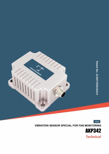
Rion AKP342 Wind Turbine Dedicated Vibration sensor
- The default address is 00. When multiple sensors are connected, each must have a unique address.
- To change the address, update all command and response data packets with the new address code.
- Example commands are provided for setting and resetting addresses.
- Common address FF can be used if the set address is forgotten.
- Baud Rate: Default is 9600. Options range from 2400 to 230400. Commands must be sent twice for changes to take effect.
- Parity Bit: Default is even parity. Options include no parity and odd parity. Changes are valid after power-up.
- Default output mode is 0 HZ. Options range from Q & A mode to 100 HZ.
- Commands must be sent twice for changes to take effect.
- Uses RTU mode with 'big-Endian' format and CRC16 for data verification.
- Default communication parameters include address 1, baud rate 9600, and even parity.
- Commands must be sent twice consecutively for reliability.
- Commands are provided to set automatic output data items, with options ranging from 10 to 100.
- Ensure a 10 ms interval between data frames for MODBUS communication.
- Parameters can only be changed once per power-up.
Catalog excerpts

AKP342 VIBRATION SENSOR FOR FAN MONITORING VIBRATION SENSOR SPECIAL FOR FAN MONITORING
Open the catalog to page 1
AKP342 VIBRATION SENSOR FOR FAN MONITORING ○ Revision Date: 2026-4-24 Note: The function, parameters and appearance of the product will be adjusted with the technical upgrade. Please contact our pre-sales business for confirmation when purchasing. Disclaimer This product is developed exclusively for commercial applications and is prohibited from being used for illegal purposes, such as military activities, research related to nuclear, chemical, or biological weapons, or any other actions that violate laws and regulations. It is strictly forbidden to engage in activities related to goods embargoed...
Open the catalog to page 2
AKP342 VIBRATION SENSOR FOR FAN MONITORING AKP342 is a high-precision, low-noise three-axis Vibration sensor specially for monitoring wind turbines. All products have been calibrated and compensated in the whole temperature range and tested for long-term stability for two weeks before leaving the factory to ensure that the best performance indicators are maintained under different working conditions and long-term test cycles. The product integrates the FFT function, which can measure the static 0HZ or 0.1 ~ 10Hz vibration, estimate the object vibration data by algorithm, and obtain the 60-second...
Open the catalog to page 3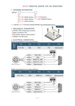
AKP342 VIBRATION SENSOR FOR FAN MONITORING ▶ ORDERING INFORMATION AKP342 Output Interface 68: 68 protocol MB: MODBUS Protocol E.g: AKP342-485-68: horizontal installation/RS485 output interface/68 protocol. ▶ MECHANICAL PARAMETERS ○ CONNECTORS: Aviation plug connector ○ Degree of protection: IP67 ○ Shell material: aluminum alloy anodized ○ Installation: four M6 screws RS232 wiring definition (5-core wiring definition) Wiring Definition Signal ground RS485 wiring definition (5-core wiring definition) Wiring Definition
Open the catalog to page 5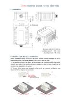
Please install the tilt sensor according to the correct method. Incorrect installation will lead to measurement errors. Pay special attention to one "surface" and two "lines": 1) The mounting surface of the sensor and the surface to be measured must be fixed tightly, smoothly and stably. If the mounting surface is uneven, it is easy to cause the error of the included angle measured by the sensor. 2) The axis of the sensor must be parallel to the axis to be measured, and the two axes should not form an angle as far as possible. MOUNTING SURFACE
Open the catalog to page 6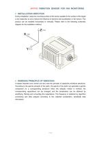
AKP342 VIBRATION SENSOR FOR FAN MONITORING ▶ INSTALLATION DIRECTION During installation, keep the mounting surface of the sensor parallel to the surface of the target to be measured, so as to reduce the influence of dynamic and acceleration on the sensor. This product can be installed horizontally or vertically. Please refer to the following schematic diagram for the installation method: ▶ WORKING PRINCIPLE OF VIBRATION It adopts imported core control unit and uses the principle of capacitive miniature pendulum. According to the gravity principle of the earth, the gravity of the earth can generate...
Open the catalog to page 7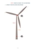
AKP342 VIBRATION SENSOR FOR FAN MONITORING ▶ LEGEND OF VIBRATION SWING MEASUREMENT
Open the catalog to page 8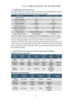
The product includes two protocols, namely, the 68 protocol and the MODBUS RTU protocol. The default configuration parameters of the protocols are as follows: MB protocol format description
Open the catalog to page 9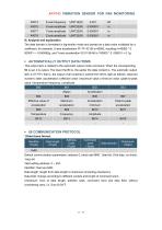
Default communication parameters: address 0, baud rate 9600, 1start bit, 8-bit data, no check, 1stop bit Valid setting address: 0 ~ 254 Identifier: fixed as 0x68; Data length: length from data length to checksum (including checksum); Data field: change according to different content and length of command word; Checksum: Sum of data length, address code, command word and data field, without considering carry, i.e. Sum & 0xFF.
Open the catalog to page 11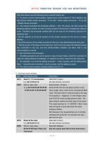
Note that please read the following items carefully before use: 1 > To ensure normal communication, please leave a time interval of 10ms between two data frames. Master sends command --10 ms idle -- Slave replies command --10 ms idle -- Master sends command 2 > The protocol specifies the broadcast address -- 255. The sensor can also accept the broadcast address content, but will not reply (except for the function of reading the address code). Therefore, the broadcast address 255 can be used for the following purposes for reference only. 1 .Set the address of all the tilt sensors of this model...
Open the catalog to page 12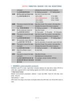
MODBUS uses RTU mode, 'big-Endian' indicates address and data items, takes CRC16 to verify data, supports 0x03 to read holding register and 0x06 to write single register. 1. Data frame format: Default communication parameters: address 1, baud rate 9600, 1start bit, 8-bit data, even parity, 1stop bit; CRC check: the range is the check of all bytes before the CRC field, and 16-bit CRC check is used.
Open the catalog to page 14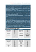
Note that please read the following items carefully before use: 1 > Because the MODBUS protocol stipulates that the time between two data frames should be at least more than 3.5 bytes (for example, under the baud rate of 9600, the time is 3.5 x (1/9600) x 11 = 0.004s). However, in order to leave enough margin, please leave a time interval of 10 ms between each data frame. Please note that the automatic output of the product does not consider the T3.5 time. Master sends command -- 10 ms idle -- Slave replies command -- 10 ms idle -- Master sends command 2 > The MODBUS protocol specifies the relevant...
Open the catalog to page 15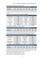
Commands must be sent twice in a row to be valid The above example is to format the byte as: one start bit + 8 data bits without parity + 1stop bit Valid after power up again. Factory default is one start bit + 8 data bits even parity + 1stop bit Note: 0009 is the register address that controls the sensor serial parity bit. 0000H: one start bit + 8 data bits even parity + 1stop bit 0001H: one start bit + 8 data bits without check + 1stop bit 0002H: one start bit + 8 data bits odd parity + 1stop bit
Open the catalog to page 16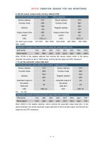
6. Set the sensor output mode: (factory default 0 HZ) Note: 0020H is the register address, which controls the automatic output data item. In the above example, the sensor automatic output data item is set to all data output, and the last two bytes are the CRC checksum.
Open the catalog to page 17All SHENZHEN RION TECHNOLOGY CO.,LTD catalogs and technical brochures
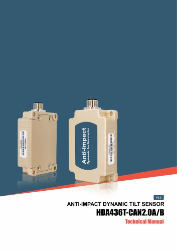 RION HDA436T TILT SENSOR
14 Pages
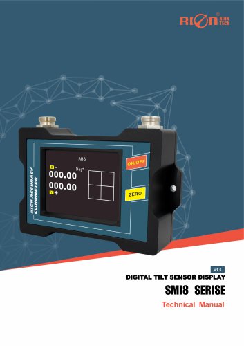 RION SMI815 SMI825
5 Pages
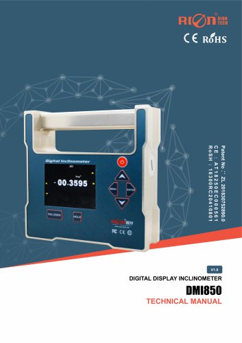 RION DMI850 inclinometer
9 Pages
 RION WCA300A
3 Pages
 RION PSI-25M
1 Page
 Rion inclinometer SDA118T
10 Pages
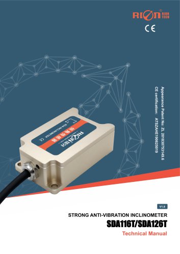 SDA116T/SDA126T
16 Pages
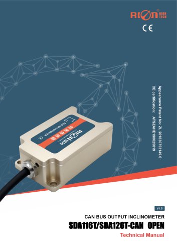 RION SDA116T/SDA126T-CAN OPEN
11 Pages
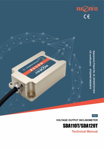 Rion SDA110T inclinometer
9 Pages
 Rion inclinometer SCA118T
10 Pages
 Rion inclinometer SCA116
16 Pages
 Rion inclinometer SCA110
10 Pages
 Rion inclinometer PCA826T
21 Pages
 Rion inclinometer MCA418T
2 Pages
 Rion inclinometer MCA416T
2 Pages
 Rion inclinometer MCA416LD
10 Pages
 Rion inclinometer MCA416L
10 Pages
 Rion inclinometer MCA416
2 Pages
 Rion inclinometer MCA410T
2 Pages
 Rion inclinometer MCA-85
12 Pages
 Rion inclinometer LCA318T
10 Pages
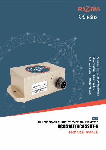 Rion HCA518T inclinometer
9 Pages
 Rion inclinometer HCA510T-N
11 Pages
 Rion inclinometer HCA510T
8 Pages
 Rion inclinometer HCA396B
11 Pages
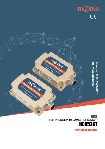 RION HDA536T INCLINOMETER
25 Pages
 HDA437T/HDA437T-CAN2.0A/B
14 Pages
 HDA437T/HDA437
25 Pages
 HDA436T
25 Pages
 HDA436T-CANOpen
28 Pages
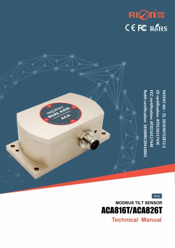 ACA816T/ACA826T
17 Pages
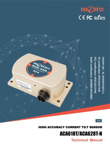 ACA618T/ACA628T-N
9 Pages
 Rion inclinometer ACA610T
9 Pages
 Rion electronic compass DDM350B
11 Pages
 Rion electronic compass DCM301B
11 Pages
 Rion electronic compass DCM250B
12 Pages
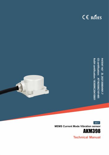 Rion AKM398 Vibration Sensor
6 Pages
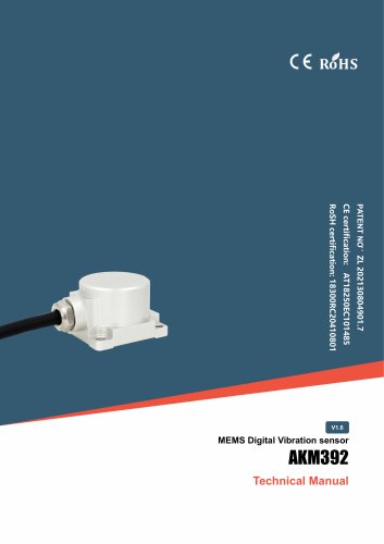 Rion AKM392 Vibration Sensor
15 Pages
 Rion AKM390 Vibration Sensor
6 Pages
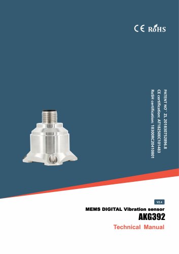 Rion Vibration Sensor AKG392
17 Pages





Archived catalogs
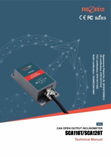
 SCA116T/SCA126T
9 Pages
- LCD screen
- Industrial monitor
- Panel-mount screen
- Pressure probe
- High-brightness monitor
- RION inclinometer
- TFT-LCD monitor
- Analog pressure sensor
- RION digital inclinometer
- Stainless steel pressure sensor
- Relative pressure sensor
- RION 2-axis inclinometer
- RION MEMS inclinometer
- RION multi-axis inclinometer
- Absolute pressure sensor
- RION analog inclinometer
- Gas pressure sensor
- Sensitive element pressure sensor
- RION high-precision inclinometer
- Liquid pressure sensor
- VirtualExpo Group
- Our Partners
- Recruitment
- Testimonials