- Catalogs
- SHENZHEN RION TECHNOLOGY CO.,LTD
- Rion acceleromwter RAM900
- Company
- Products
- Catalogs
- News & Trends
- Exhibitions
Rion acceleromwter RAM900
1 /37Pages

Rion acceleromwter RAM900
1 /37Pages
Catalog excerpts

Technical Manual ○INCLINOMETER ○3D COMPASS ○ACCELEROMETER ○GYRO ○NORTH FINDER ○INS&IMU RION TECHNOLOGY SINCE2008 · SENSING AND INDUSTRIAL CONTR
Open the catalog to page 1
RION QUALIFICATION CERTIFICATION ○ Quality Management System Certification: IATF16949:2016 (Certificate No.: T178487) ○ Intellectual property management system certification: GB/T29490-2013 standard (certificate No.: 41922IP00281-06R0M) ○ GJB9001C-2017 standard weapons and equipment quality management system certification (registration No.: 02622J31799R0M) ○ High-tech enterprise (Certificate No.: GR201844204379) ○ Shenzhen Specialized Special New Enterprise (No.: SZ20210879) ○ Revision date: 2023-9-21 Note: Product functions, parameters, appearance, etc. will be adjusted as the technology upgrades,...
Open the catalog to page 2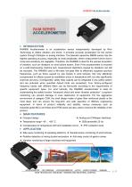
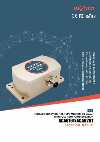
RAM900 Accelerometer is an acceleration sensor independently developed by Rion Technology to detect vibration and shock. It provides accurate acceleration for the control system through CANopen or analog interface. The selected capacitive MEMS sensor has the highest operating accuracy, especially at small amplitudes, where measurement errors due to cross-axis sensitivity are negligible. Therefore, the RAM900 is ideal for the precise acquisition of vibration, such as vibrations on wind turbine towers. Even if the accelerometer is mounted on a solid load-bearing machine part, measurement distortions...
Open the catalog to page 3
Power-on repeatability Bias temperature coefficient Long-term stability Response time Response frequency Range Axis Bias calibration Resolution Full tempe.e range working accuracy Power-on start time 3DB bandwidth Output signal 25Hz CANopen, Analog(current 4~20mA),Switch (relay switch) Supply voltage Supply current Relay switching threshold Note: CAN bus terminal resistance can be added on request, or remark can be added to PCBA. ▶ SWITCH OUTPUT CONTROL Relay switching maximum voltage: 30VDC Relay switching maximum current: 1.0A Relay: Under normal circumstances, after the device is powered on,...
Open the catalog to page 4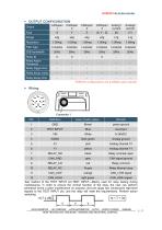
▶ OUTPUT CONFIGURATION CANopen 1 Filter type Relay Action Threshold Relay trigger time Relay decay value Relay decay time Output Axial Range *Different configurations are available upon request. Color (if with cable) power ground TEST INPUT* test input Dark green Analog ground Relay normally open Relay common Relay Normal close CAN_LOW signal light green CAN_HIGH signal Test method of the TEST INPUT pin:TEST INPUT---Mainly used for relay testing during maintenance. In order to ensure the normal function of the relay, the user can perform periodical (once a year) maintenance on purpose, and can...
Open the catalog to page 5
○INCLINOMETER ○3D COMPASS ○ACCELEROMETER ○GYRO ○NORTH FINDER ○INS&IMU RION TECHNOLOGY SINCE2008 · SENSING AND INDUSTRIAL CON
Open the catalog to page 6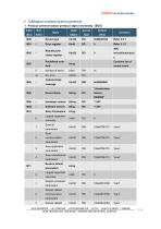
▶ CANopen communication protocol 1. Product communication protocol object dictionary(EDS) Index Device type Error register Manufacturer status register Predefined error recent errors errors/timeouts,et Contains list of COB-ID SYNC Device Name Hardware version Software version Store Parameters Largest supported sub-index Save all parameters Save communication parameters Save application parameters Save manufacturer parameters Restore default Largest supported sub-index Restore all default parameters communication parameters Restore default ○INCLINOMETER ○3D COMPASS ○ACCELEROMETER ○GYRO ○NORTH...
Open the catalog to page 7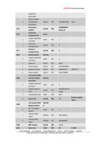
RAM900 Accelerometer application parameters Restore default 4 COB-ID Consumer Largest supported sub-index Consumer heartbeat time Producer heartbeat time Identity object Largest supported sub-index Product code Revision number Serial number Largest supported sub-index COB-ID used by PDO Transmission type Event time Mapped Object NO. of mapped objects Transmit PDO object Transmit PDO object Baud rate ○INCLINOMETER ○3D COMPASS ○ACCELEROMETER ○GYRO ○NORTH FINDER ○INS&IMU RION TECHNOLOGY SINCE2008 · SENSING AND INDUSTRIAL C
Open the catalog to page 8
2. Detailed specification of communication protocol objects 2.1Communication Profile Area(communication protocol area) 2.1.1OD Index(0x1000): Device Type(device type, UINT32, RO) I. Query device type SDO request message format CAN-ID 0x600+ Node_ID SDO Response message format CAN-ID 0x580+ Node_ID Note:Device Type = 0x0004019A. 2.1.2 OD Index(0x1001): Error Register(error register, UINT8, RO) I. Query the content of the error register and save the latest error type. SDO request message format CAN-ID 0x600+ Node_ID SDO response message format CAN-ID 0x580+ Node_ID Note: Error Register = 0x10,A...
Open the catalog to page 9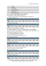
device profile specific manufacturer specific OD Index(0x1002): Manufacturer status Register (Factory Defined Error Status Register, UINT32, RO) I. Query the content of the error status register defined by the manufacturer. SDO request message format CAN-ID 0x600+ Node_ID SDO response message format CAN-ID 0x580+ Node_ID Note: Manufacturer status Register = 0x00000000. 2.1.4 OD Index(0x1003): Pre-defined error field(pre-defined error field, ARRAY) This object represents errors generated on the CANopen sensor, programmed by the emergency object, and provides error history. 2.1.4.1 Sub-Index:0x00(Number...
Open the catalog to page 10
RAM900 Accelerometer Note: Clear Number of errors. 2.1.4.2 Sub-Index:0x01(the 1st error,UINT32, RO) A. Query the first error code of Sub-Index 0x01 If the content of sub-index 0x00 is not zero, it indicates the number of errors that have occurred in the sensor, where the content of sub-index 0x01 is the latest error code, 0x02 is the next most recent error code, and so on. SDO request message format CAN-ID 0x600+ Node_ID SDO response message format CAN-ID 0x580+ Node_ID Note: Error Code = 0x03008100. The upper 16 bits of the Error Code are composed of additional information and the lower 16 bits...
Open the catalog to page 11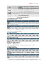
RAM900 Accelerometer The CANopen device does not generate synchronization Frame 29 bits CAN-ID 11 bits CAN-ID The CANopen device generates synchronization messages 11-bit CAN-ID is valid (CAN standard frame) 29-bit CAN-ID is valid (CAN extended frame) 29-bit extended frame CAN-ID 11-bit standard frame CAN-ID Synchronous COB-ID description A. Query COB-ID synchronization message SDO request message format CAN-ID 0x600+ Node_ID SDO response message format CAN-ID 0x580+ Node_ID Note: The synchronization COB-ID is: 0x00000080. A. Set COB-ID synchronization message SDO request message format CAN-ID...
Open the catalog to page 12All SHENZHEN RION TECHNOLOGY CO.,LTD catalogs and technical brochures
 Excavator 3D guidance system
7 Pages
 RION WCA300A
3 Pages
 RION PSI-25M
1 Page
 Rion inclinometer SDA118T
10 Pages
 SDA116T/SDA126T
16 Pages
 SDA116T/SDA126T-CAN OPEN
11 Pages
 Rion inclinometer SDA110T
9 Pages
 Rion inclinometer SCA118T
10 Pages
 SCA116T/SCA126T (2025)
11 Pages
 Rion inclinometer SCA116
16 Pages
 Rion inclinometer SCA110
10 Pages
 Rion inclinometer PCA826T
21 Pages
 Rion inclinometer MCA418T
2 Pages
 Rion inclinometer MCA416T
2 Pages
 Rion inclinometer MCA416LD
10 Pages
 Rion inclinometer MCA416L
10 Pages
 Rion inclinometer MCA416
2 Pages
 Rion inclinometer MCA410T
2 Pages
 Rion inclinometer MCA-85
12 Pages
 Rion inclinometer LCA318T
10 Pages
 LCA316T/LCA326T
16 Pages
 LCA316T/LCA326T-CAN OPEN
11 Pages
 Rion inclinometer HCA518T
9 Pages
 HCA518T&HCA528T
8 Pages
 HCA516T/HACA526T-CAN
10 Pages
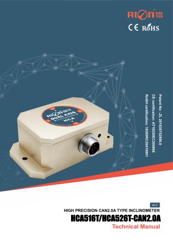 HCA516T/HACA526T-CAN2.0A
9 Pages
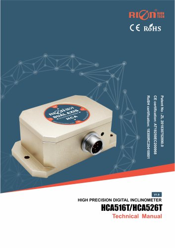 HCA516T/HCA526T
16 Pages
 Rion inclinometer HCA510T-N
11 Pages
 Rion inclinometer HCA510T
8 Pages
 Rion inclinometer HCA396B
11 Pages
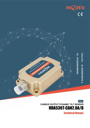 HDA536T-CAN2.0A/B
17 Pages
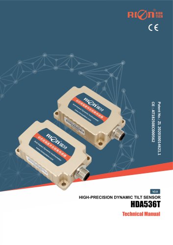 HDA536T
25 Pages
 HDA437T/HDA437T-CAN2.0A/B
14 Pages
 HDA437T/HDA437
25 Pages
 HDA436T
25 Pages
 HDA436T-CANOpen
28 Pages
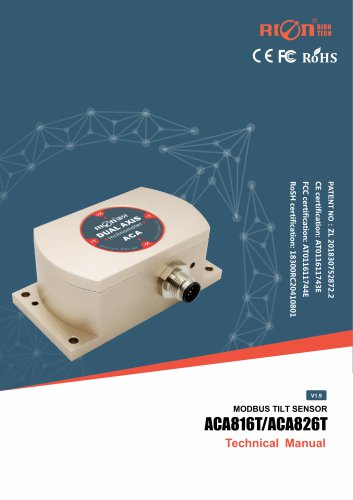 ACA816T/ACA826T
17 Pages
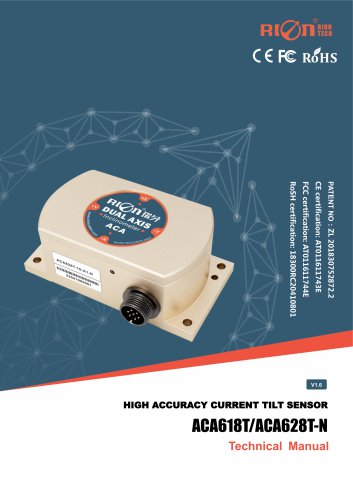 ACA618T/ACA628T-N
9 Pages
 Rion inclinometer ACA610T
9 Pages
 Rion electronic compass DDM350B
11 Pages
 Rion electronic compass DCM301B
11 Pages
 Rion electronic compass DCM250B
12 Pages
 Rion acceleromwter RAM900S
39 Pages
 Rion acceleromwter AKM398
6 Pages
 Rion acceleromwter AKM392
15 Pages
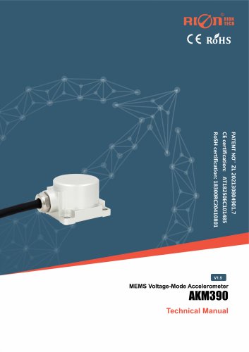 Rion Vibration Sensor AKM390
6 Pages
 Rion acceleromwter AKG392
17 Pages


Archived catalogs
 SCA116T/SCA126T
9 Pages
- LCD screen
- Industrial monitor
- Panel-mount screen
- Pressure probe
- High-brightness monitor
- TFT-LCD monitor
- Analog pressure sensor
- Single-axis accelerometer
- Red Rooster 3-axis accelerometer
- Red Rooster digital inclinometer
- Relative pressure sensor
- Stainless steel pressure sensor
- Compact accelerometer
- Red Rooster 2-axis inclinometer
- Red Rooster MEMS inclinometer
- General purpose accelerometer
- Red Rooster accelerometer with analog output
- Red Rooster multi-axis inclinometer