- Catalogs
- SHENZHEN RION TECHNOLOGY CO.,LTD
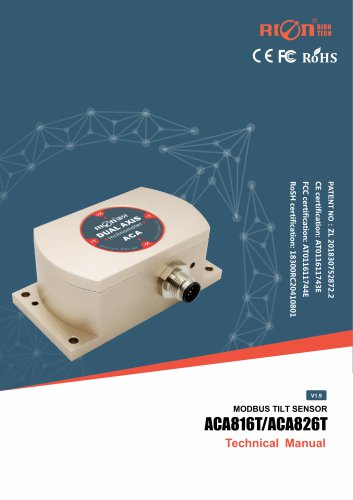
- HDA437T/HDA437T-CAN2.0A/B
- Company
- Products
- Catalogs
- News & Trends
- Exhibitions
HDA437T/HDA437T-CAN2.0A/B
1 /14Pages

HDA437T/HDA437T-CAN2.0A/B
1 /14Pages
Catalog excerpts

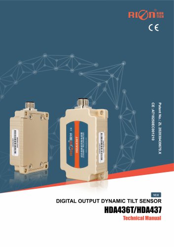
HDA436T/HDA437T-CAN2.0A/B OUTPUT DYNAMIC TILT SENSOR ANTI-IMPACT DYNAMIC TILT SENSOR
Open the catalog to page 1
HDA436T/HDA437T-CAN2.0A/B OUTPUT DYNAMIC TILT SENSOR RION QUALIFICATION CERTIFICATION ○ China National Intellectual Property Appearance Patent (Patent No.: ZL 202030439670. X) ○ CE CERTIFICATION: Registration No. AT18250EC001210 ○ Revision Date: 2024-9-9 Note: The function, parameters and appearance of the product will be adjusted with the technical upgrade. Please contact our pre-sales business for confirmation when purchasing. Disclaimer This product is developed exclusively for commercial applications and is prohibited from being used for illegal purposes, such as military activities, research...
Open the catalog to page 2
HDA436T/HDA437T-CAN2.0A/B OUTPUT DYNAMIC TILT SENSOR ▶ PRODUCT DESCRIPTION The HDA436T/HDA437T product is a new generation of digital MEMS dynamic tilt sensor launched by RION Technology, which can measure the attitude parameters (roll, pitch, and azimuth) of a moving carrier and is suitable for tilt measurement in motion or vibration states. The HDA436T is equipped with built-in acceleration and gyroscope sensors, and integrates the Kalman filter algorithm to measure real-time motion data of the carrier under motion or vibration conditions. The product has dual CAN (CAN2.0A/CAN2.0B) modes and...
Open the catalog to page 3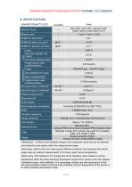
HDA436T/HDA437T-CAN2.0A/B OUTPUT DYNAMIC TILT SENSOR ▶ SPECIFICATIONS HDA436T/HDA437T-C2/C3 Measure range Roll ±180°, pitch ±90°, azimuth ±180° (initial value at power-down is 0°) Measure axis X axis / Y axis / Z axis Roll&Pitch Dynamic accuracy Zero bias stability (10s mean) Zero Bias Instability(allan) Angle random walk coefficient(allan) Bias instability(allan) Speed random walk coefficient(allan) Zero point temp. Coefficient3) Power-on startup time Response time Output signal Electromagnetic compatibility Insulation resistance Impact resistance ≥100 Megohm 100g @ 11ms, 3 axial direction (half...
Open the catalog to page 4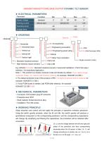
HDA436T/HDA437T-CAN2.0A/B OUTPUT DYNAMIC TILT SENSOR ▶ ELECTRICAL PARAMETERS Parameter Supply voltage Working current without load Operating temp storage temp EV: Engineering excavators EGP:Engineering gravel piling V:Vehicle MTI:Mine Truck inclination 6: Standard industrial scenario 7: High-intensity impact scenario Protection Grade Application industry Output Interface Installation Direction Application scenario S: Single connector (male) E.g: HDA436T-C2-OB:Standard industrial scenario / Horizontal Installation / CAN 2.0A output interface / On-board/ship Application. Note: 1. This product is...
Open the catalog to page 5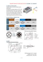
HDA436T/HDA437T-CAN2.0A/B OUTPUT DYNAMIC TILT SENSOR ▶ INSTALLATION AXIAL HDA436T follows the NED coordinate system, right-handed. According to the rotation sequence of ZYX, when the positive direction of the X axis is directed to the front of the carrier, the rotation angle around the Z axis is the heading angle, the rotation angle around the Y axis is the pitch angle, and the rotation angle around the X axis is the roll angle. ▶ ELECTRICAL CONNECTION Definition of male wiring PIN DEFINITION 9~36V Power supply positive GND Power supply Negative Definition of female wiring PIN DEFINITION 9~36V...
Open the catalog to page 6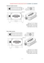
HDA436T/HDA437T-CAN2.0A/B OUTPUT DYNAMIC TILT SENSOR Shell size of double connector Shell size: 72 × 47 × 22.5mm Installation size: 64 × 39 × 6.5mm Mounting screws: 4 M4 screws Shell material: aluminum alloy Size of single connector Shell size: 72 × 47 × 22.5mm Installation size: 64 × 39 × 6.5mm Mounting screws: 4 M4 screws Shell material: aluminum alloy
Open the catalog to page 7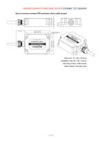
HDA436T/HDA437T-CAN2.0A/B OUTPUT DYNAMIC TILT SENSOR Size of corrosion-resistant IP68 protection direct outlet product Shell size: 72 × 56 × 24.5mm Installation size: 64 × 39 × 6.5mm Mounting screws: 4 M4 screws Shell material: 304 alloy steel
Open the catalog to page 8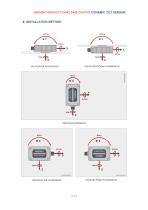
HDA436T/HDA437T-CAN2.0A/B OUTPUT DYNAMIC TILT SENSOR ▶ INSTALLATION METHOD
Open the catalog to page 9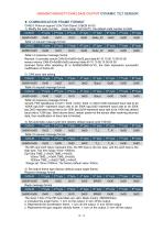
HDA436T/HDA437T-CAN2.0A/B OUTPUT DYNAMIC TILT SENSOR ▶ COMMUNICATION FRAME FORMAT CAN2.0 Protocol support 2.0A(11bit ID)and 2.0B(29 bit ID) 1) Modify the node number. (node range: 0x01-0x7F), the default node number is 0x05 CAN-ID 1st byte 2nd byte 3rd byte 4th byte 5th byte 6th byte 7th byte 8th byte 0x600+0x05 0x40 0x10 0x10 Table1-3 request message format CAN-ID 1st byte 2nd byte 3rd byte 0x580+0x05 Table1-4 response message format Remark: if controller sends CAN-ID=0x600+0x05,sent data:40 10 10 00 10 00 00 00 sensor returns CAN-ID=0x580+0x05,returned data:40 10 10 00 10 00 00 00 received...
Open the catalog to page 10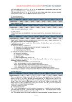
HDA436T/HDA437T-CAN2.0A/B OUTPUT DYNAMIC TILT SENSOR The host sends: 40 30 10 00 07 00 00 00, the angle frame, acceleration frame and gyro angular velocity frame output will be turned on. The host sends: 40 30 10 00 05 00 00 00, will turn on the angle frame and gyro angular velocity frame output, and turn off the acceleration frame output. 5) Azimuth clear zero Request message format CAN-ID 1st byte 2nd byte 0x600+0x05 0x40 Reply message format CAN-ID 1st byte 0x580+0x05 0x40 0x10 0x10 Clear the current azimuth angle to zero. 6) Data analysis 1. Data frame types are divided into three types:...
Open the catalog to page 11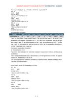
HDA436T/HDA437T-CAN2.0A/B OUTPUT DYNAMIC TILT SENSOR The result is the angle. Eg,XL=0x26,XH=0x15,angle is 54.14° XH XL 0x15 0x26 0x1526( 5414 ) Final result:5414/100=54.14° YH YL 0xEA 0xDA 0xEADA( -5414 ) Final result:-5414/100=-54.14° ZH ZL 0x23 0x28 0x2328( 9000 ) Final result:9000/100=90.00° Temp 0x19(25) = 25° Celsius. B: Acceleration data frame CAN-ID 1st byte 2nd byte 0x580+Node_ID There are eight bytes of data behind CAN-ID. The first two bytes are XL, XH is the X-axis acceleration, the third and fourth bytes are YL, YH is the Y-axis acceleration, and the fifth and sixth bytes ZL and ZH...
Open the catalog to page 12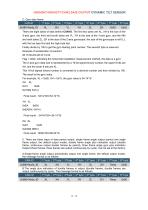
HDA436T/HDA437T-CAN2.0A/B OUTPUT DYNAMIC TILT SENSOR C: Gyro data frame CAN-ID 1st byte 0x580+Node_ID There are eight bytes of data behind CAN-ID. The first two bytes are XL, XH is the size of the X-axis gyro, the third and fourth bytes are YL, YH is the size of the Y-axis gyro, and the fifth and sixth bytes ZL, ZH is the size of the Z-axis gyroscope; the size of the gyroscope is int16_t, with the low byte first and the high byte last. Finally divide by 100 to get the gyro floating point number. The seventh byte is reserved. Example of acceleration conversion: 26 15 DA EA 28 23 19 02 Flag = 0x02,...
Open the catalog to page 13All SHENZHEN RION TECHNOLOGY CO.,LTD catalogs and technical brochures
 Excavator 3D guidance system
7 Pages
 RION WCA300A
3 Pages
 RION PSI-25M
1 Page
 Rion inclinometer SDA118T
10 Pages
 SDA116T/SDA126T
16 Pages
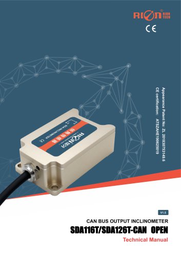 SDA116T/SDA126T-CAN OPEN
11 Pages
 Rion inclinometer SDA110T
9 Pages
 Rion inclinometer SCA118T
10 Pages
 SCA116T/SCA126T (2025)
11 Pages
 Rion inclinometer SCA116
16 Pages
 Rion inclinometer SCA110
10 Pages
 Rion inclinometer PCA826T
21 Pages
 Rion inclinometer MCA418T
2 Pages
 Rion inclinometer MCA416T
2 Pages
 Rion inclinometer MCA416LD
10 Pages
 Rion inclinometer MCA416L
10 Pages
 Rion inclinometer MCA416
2 Pages
 Rion inclinometer MCA410T
2 Pages
 Rion inclinometer MCA-85
12 Pages
 Rion inclinometer LCA318T
10 Pages
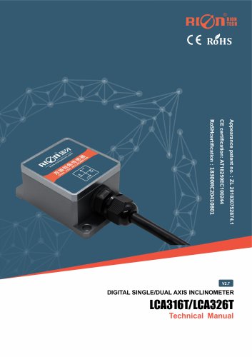 LCA316T/LCA326T
16 Pages
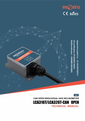 LCA316T/LCA326T-CAN OPEN
11 Pages
 Rion inclinometer HCA518T
9 Pages
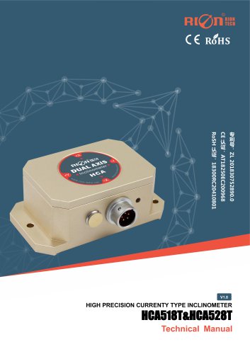 HCA518T&HCA528T
8 Pages
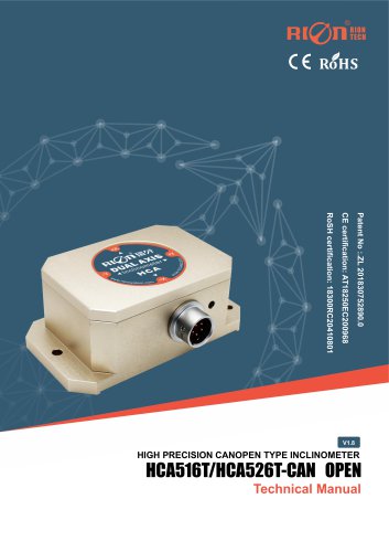 HCA516T/HACA526T-CAN
10 Pages
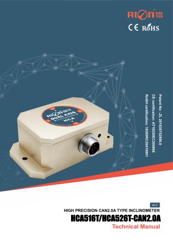 HCA516T/HACA526T-CAN2.0A
9 Pages
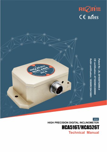 HCA516T/HCA526T
16 Pages
 Rion inclinometer HCA510T-N
11 Pages
 Rion inclinometer HCA510T
8 Pages
 Rion inclinometer HCA396B
11 Pages
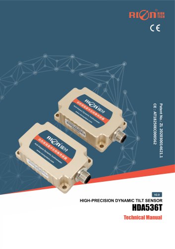
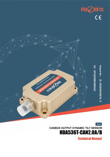 HDA536T-CAN2.0A/B
17 Pages
 HDA536T
25 Pages
 HDA437T/HDA437
25 Pages
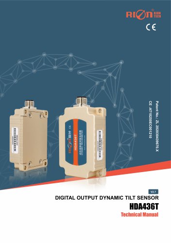 HDA436T
25 Pages
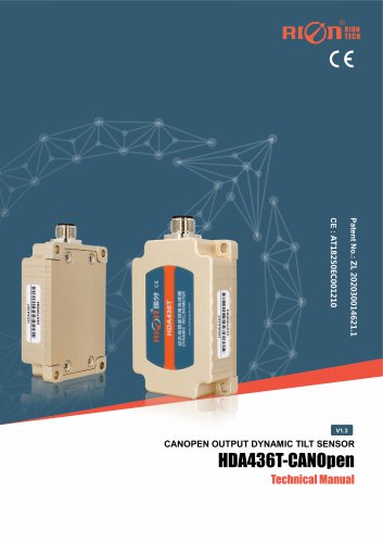 HDA436T-CANOpen
28 Pages
 ACA816T/ACA826T
17 Pages
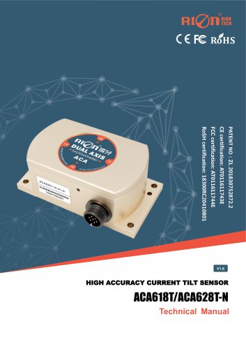 ACA618T/ACA628T-N
9 Pages
 Rion inclinometer ACA610T
9 Pages
 Rion electronic compass DDM350B
11 Pages
 Rion electronic compass DCM301B
11 Pages
 Rion electronic compass DCM250B
12 Pages
 Rion acceleromwter RAM900S
39 Pages
 Rion acceleromwter RAM900
37 Pages
 Rion acceleromwter AKM398
6 Pages
 Rion acceleromwter AKM392
15 Pages
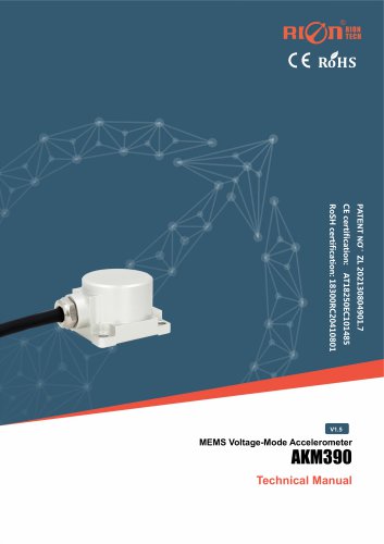 Rion Vibration Sensor AKM390
6 Pages
 Rion acceleromwter AKG392
17 Pages


Archived catalogs
 SCA116T/SCA126T
9 Pages
- LCD screen
- Industrial monitor
- Panel-mount screen
- Red Rooster accelerometer
- Pressure probe
- High-brightness monitor
- Red Rooster inclinometer
- TFT-LCD monitor
- Analog pressure sensor
- Single-axis accelerometer
- Red Rooster 3-axis accelerometer
- Red Rooster digital inclinometer
- Relative pressure sensor
- Stainless steel pressure sensor
- Compact accelerometer
- Red Rooster 2-axis inclinometer
- Red Rooster MEMS inclinometer
- General purpose accelerometer
- Red Rooster accelerometer with analog output
- Red Rooster multi-axis inclinometer