
- Catalogs
- SHENZHEN RION TECHNOLOGY CO.,LTD
- RION AKG392 MEMS DIGITAL VIBRATION SENSOR


RION AKG392 MEMS DIGITAL VIBRATION SENSOR
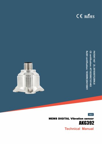
RION AKG392 MEMS DIGITAL VIBRATION SENSOR
The AKG392 is a three-axis MEMS digital vibration sensor designed for applications such as vibration and impact testing. It features digital interface outputs (RS232/485/TTL) and supports multi-point measurement and data analysis through internal FFT processing. The sensor is constructed with a single crystal silicon capacitive sensor, low-power ASIC, microprocessor, and temperature sensor, ensuring low power consumption and stable output.
- Three-axis measurement (X, Y, Z)
- Output signals: RS232, RS485, TTL
- Power supply: 9-36V
- Operating temperature: -40°C to +85°C
- Size: 34.3×34.3×38.5mm
- Excellent deviation stability and environmental performance
The sensor is suitable for use in medical equipment, bridges, large machinery, engines, automobiles, road rollers, crash records, fatigue monitoring, wind power generation, low-frequency vibration monitoring, traffic system monitoring, roadbed analysis, and high-speed railway fault detection.
- Measurement range: ±2g to ±40g
- Bias calibration: <1mg
- Power on/off repeatability: <2mg
- Bandwidth: 500Hz
- Output rate: 5Hz to 1000Hz
- Protocols: RION 68 and MODBUS RTU
The sensor provides data on vibration frequency, speed, and displacement, with a frequency resolution of 4Hz.
Example: AKG392-02-T-68 indicates RS232 output, ±2g measure range, standard installation, and RION 68 protocol.
Includes a magnetic base and L-type pinboard for installation.
Details the wiring colors and functions for GND, RS232/RS485, and Vcc.
The sensor supports automatic data output and uses RION 68 and MODBUS RTU protocols. It includes detailed command word analysis for reading acceleration, frequency, speed, amplitude, and temperature data.
Data output is configurable based on BIT settings, with options for acceleration, frequency, speed, amplitude, and temperature.
Describes the data frame format, command word analysis, and setting operations for communication and data output.
The document outlines various commands and specifications for the AKG392 MEMS Digital Vibration Sensor. Key commands include setting the sensor address, reading software version, and setting save instructions. The address ranges from 00 to EF, with a common address of FF for all products. Commands must be sent twice consecutively to be effective.
The sensor uses the MODBUS protocol in RTU mode with 'big-Endian' representation. Default communication parameters include address 1, baud rate 9600, and even parity. The protocol requires a minimum 10ms interval between data frames. Broadcast address 0 can be used for setting addresses and testing sensors.
Data types include short, ushort, int, and uint, with specific register addresses for temperature, acceleration, vibration frequency, speed, and amplitude. Data is calculated by multiplying register data by a coefficient.
Examples are provided for reading X-axis data, setting sensor address, baud rate, parity bit, output mode, auto-output data, and bandwidth. Each example includes host commands and expected slave responses, with CRC checksums for validation.
Settings are not saved after power-off unless a save command is issued. The process involves sending a setting command, receiving a success response, and then issuing a save command.
Commands must be sent twice consecutively to be effective. The document emphasizes the importance of timing and CRC checks for reliable communication.
Catalog excerpts
AKG392 MEMS DIGITAL Vibration sensor MEMS DIGITAL Vibration sensor
Open the catalog to page 1
AKG392 MEMS DIGITAL Vibration sensor ○ CE certification: AT18250EC101483 ○ RoHS certification: 18300RC20410801 ○ China National Intellectual Property Appearance Patent (Patent No.: ZL 201830752896.8) ○ Revision time:2026-7-6 Note: Product functions, parameters, appearance, etc. will be adjusted as the technology upgrades. Please contact our pre-sales business to confirm when purchasing. Disclaimer This product is developed exclusively for commercial applications and is prohibited from being used for illegal purposes, such as military activities, research related to nuclear, chemical, or biological...
Open the catalog to page 2
► INTRODUCTION AKG392 three-axis vibration sensor is a product independently developed and produced, applied in wide range of applications, which covers many fields such as vibration testing and impact testing. The product adopts digital interface output with options as RS232/485/TTL. Different address codes can be set, multiple Vibration sensor can be installed in series for long distance, which is convenient for multi-point measurement and data analysis. Internal FFT processing can directly output the object vibration frequency and speed and Amplitude, convenient for users to analyze data....
Open the catalog to page 3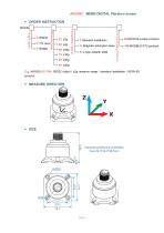
AKG392 MEMS DIGITAL Vibration sensor ▶ ORDER INSTRUCTION AKG39 T: Standard installation A: Magnetic adsorption base B: L-type adapter plate Communicating Protocol Installation method Measure range Output signal 68:RION 68 custom protocol MB:MODBUS RTU protocol 40: ±40g E.g: AKG392-02-T-68: RS232 output / ±2g measure range / standard installation / RION 68 protocol.
Open the catalog to page 5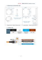
Magnetic base Material: Stainless steel L-type pinboard Material: aluminum alloy
Open the catalog to page 6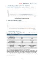
AKG392 MEMS DIGITAL Vibration sensor ► SENSITIVITY AMPLITUDE-FREQUENCY RESPONSE CHARACTERISTIC CURVE (reference conditions: f=20.000Hz, a=2.000G) ► SENSITIVITY LINEARITY GRAPH The product includes 68 protocol and MODBUS RTU two protocols. The default configuration parameters of the protocol are as follows:__ RION 68 protocol and MODBUS protocol mutual switching method: Open the serial port debugging assistant, select the baud rate 115200, no parity, stop bit 1, the connection port number, make the host computer send hexadecimal 0xAA regularly for every 10ms. Power on the product and reply "RION"...
Open the catalog to page 7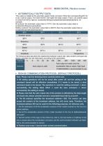
This output is related to the automatic output mode command. When the corresponding BIT bit is set, it will be output. The lower the BIT, the higher the data content. That is, all content output is sorted from left to right as: acceleration|frequency|speed|amplitude|temperature. for example: 68 protocol: the automatic output item is 1011H, then the automatic output data is: acceleration|frequency|amplitude; Modbus protocol: the automatic output item is 9001H, then the automatic output data is: acceleration|amplitude|temperature.___ The following table describes the relationship between output...
Open the catalog to page 8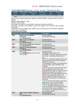
1.DATA FRAME FORMAT:(8 bits date, 1 bit stop, No check, Default baud rate 9600) Default communication parameters: address 0, baud rate 9600, 1 start bit, 8 data, no parity, 1 stop bit; Effective setting address: 0~254; Data length: the length from data length to checksum (including checksum); Data field: according to the different content and length of the command word changes accordingly; Checksum: The sum of data length, address code, command word and data field, regardless of carry, that is, Sum&0xFF. Command Meaning/Example Description 0X01 Read X axis acceleration Data field (0byte) command....
Open the catalog to page 9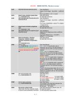
Sensor reply Signed 16-bit integer, big endian, coefficient 0.1 No data field command Data field(6byte) Signed 32-bit integer, big endian, coefficient 0.000001 Read triaxial vibration amplitude Data field (0byte) data No data field command Read acceleration, vibration Data field (0byte) frequency, vibration speed, No data field command Vibration amplitude, temperature data Blue is X, Y, Z acceleration data in sequence, the unit is g, the data analysis is consistent with the 04H command analysis method Green is X, Y, Z frequency data in sequence, the unit is Hz, the data analysis method is consistent...
Open the catalog to page 10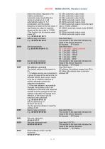
before the sensor responds to the relative acceleration. Automatic output mode:After the sensor is powered on, it will automatically output X, Y, Z acceleration, and the output frequency is based on the set value. If high frequency output is required, please set the baud rate to 115200. (This function can be memory when power off) The default address of the sensor is 00, 1. If multiple sensors are connected to a group of buses at the same time, for example RS485: each sensor needs to be set to a different address to achieve separate control and response acceleration. 2. If the new address is...
Open the catalog to page 11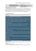
Data field (BYTE) The number in the data field indicates the result of the sensor response AKG392T_V210708A Setting instructions and procedures All setting operations are not saved when the power is turned off. The setting is effective imm ediately once comand sent. If you need to save setting command after power off, you need to issue a save command. The operation is:Issue the setting command -> return success, the se tting takes effect -> issue the save command -> return success, the setting is saved. MODBUS uses RTU mode, ‘big-Endian’ represents addresses and data items, adopts CRC16 check...
Open the catalog to page 12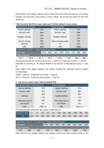
Note: 0012H is the register address, which controls the baud rate of the sensor. In the above example, the baud rate of the sensor is set to 19200, and the last two bytes are the CRC checksum. 7.Set the parity bit of the sensor serial port: (factory default is even parity) Note: 0013H is the register address, this register controls the sensor output mode. In the
Open the catalog to page 15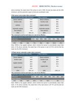
above example, the output rate of the sensor is set to 10HZ, the last two bytes are the CRC checksum, and the automatic output is three-axis acceleration data. 9.Set sensor auto-output data command : Note: 0000H is the register address, which controls the sensor to automatically output data items. In the above example, the output item of the read sensor is 9111H, and the last two bytes are the CRC checksum.
Open the catalog to page 16All SHENZHEN RION TECHNOLOGY CO.,LTD catalogs and technical brochures
 RION HDA436T TILT SENSOR
14 Pages
 RION SMI815 SMI825
5 Pages
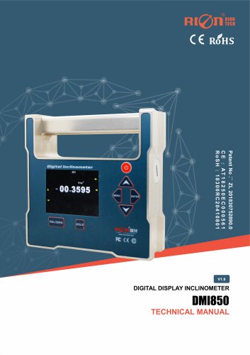 RION DMI850 inclinometer
9 Pages
 RION WCA300A
3 Pages
 RION PSI-25M
1 Page
 Rion inclinometer SDA118T
10 Pages
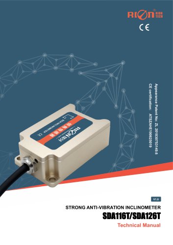 SDA116T/SDA126T
16 Pages
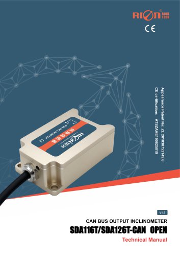 RION SDA116T/SDA126T-CAN OPEN
11 Pages
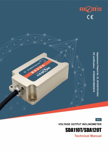 Rion SDA110T inclinometer
9 Pages
 Rion inclinometer SCA118T
10 Pages
 Rion inclinometer SCA116
16 Pages
 Rion inclinometer SCA110
10 Pages
 Rion inclinometer PCA826T
21 Pages
 Rion inclinometer MCA418T
2 Pages
 Rion inclinometer MCA416T
2 Pages
 Rion inclinometer MCA416LD
10 Pages
 Rion inclinometer MCA416L
10 Pages
 Rion inclinometer MCA416
2 Pages
 Rion inclinometer MCA410T
2 Pages
 Rion inclinometer MCA-85
12 Pages
 Rion inclinometer LCA318T
10 Pages
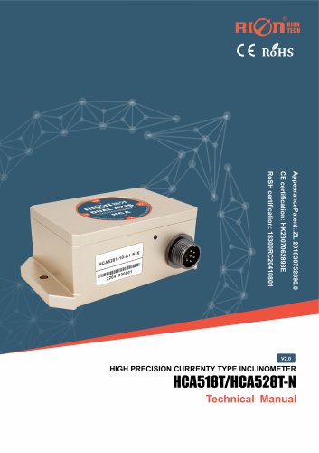 Rion HCA518T inclinometer
9 Pages
 Rion inclinometer HCA510T-N
11 Pages
 Rion inclinometer HCA510T
8 Pages
 Rion inclinometer HCA396B
11 Pages
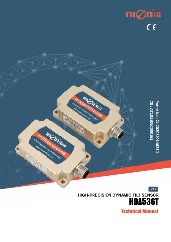 RION HDA536T INCLINOMETER
25 Pages
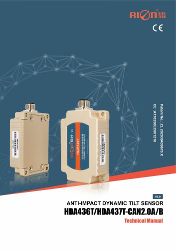 HDA437T/HDA437T-CAN2.0A/B
14 Pages
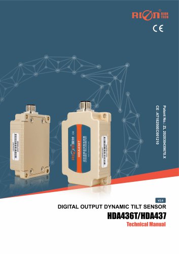 HDA437T/HDA437
25 Pages
 HDA436T
25 Pages
 HDA436T-CANOpen
28 Pages
 ACA816T/ACA826T
17 Pages
 ACA618T/ACA628T-N
9 Pages
 Rion inclinometer ACA610T
9 Pages
 Rion electronic compass DDM350B
11 Pages
 Rion electronic compass DCM301B
11 Pages
 Rion electronic compass DCM250B
12 Pages
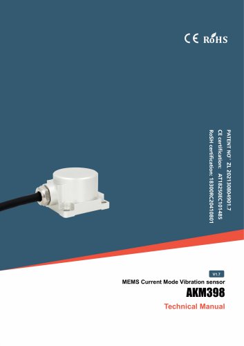 Rion AKM398 Vibration Sensor
6 Pages
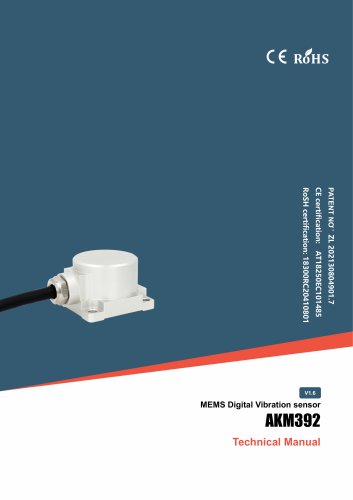 Rion AKM392 Vibration Sensor
15 Pages
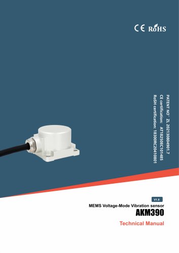 Rion AKM390 Vibration Sensor
6 Pages
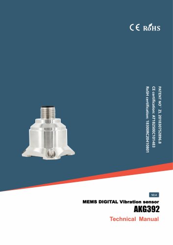 Rion Vibration Sensor AKG392
17 Pages




Archived catalogs
 SCA116T/SCA126T
9 Pages
- LCD screen
- Industrial monitor
- Panel-mount screen
- Pressure probe
- High-brightness monitor
- RION inclinometer
- TFT-LCD monitor
- Analog pressure sensor
- RION digital inclinometer
- Stainless steel pressure sensor
- Relative pressure sensor
- RION 2-axis inclinometer
- RION MEMS inclinometer
- RION multi-axis inclinometer
- Absolute pressure sensor
- RION analog inclinometer
- Gas pressure sensor
- Sensitive element pressure sensor
- RION high-precision inclinometer
- Liquid pressure sensor