
- Catalogs
- SHENZHEN RION TECHNOLOGY CO.,LTD
- RION AKC378 MEMS current-type vibration sensor


RION AKC378 MEMS current-type vibration sensor
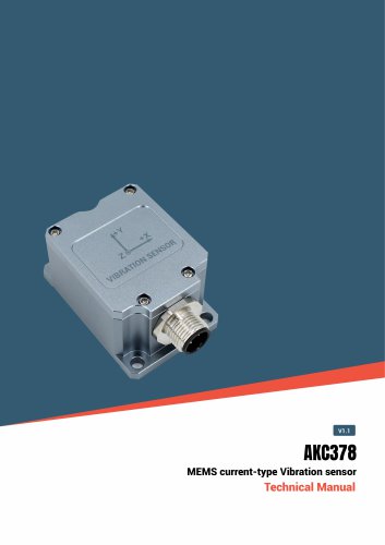
RION AKC378 MEMS current-type vibration sensor
The AKC378 is a MEMS-based vibration sensor with a 4-20mA current output, utilizing single-crystal silicon capacitive sensing technology. It features low-noise micro-mechanical capacitive sensing elements and a built-in signal compensation circuit for excellent linearity and stability. The sensor is designed for industrial applications, offering a frequency response from 0Hz to 200Hz and a selectable measuring range of ±2g to ±16g.
Key Features
- Three-axis MEMS vibration sensor with 4-20mA output
- Wide operating temperature range: -40 to +85℃
- Measurement range: ±2g to ±16g
- Self-test function
- Protection rating: IP67
Application Scope
- Bridge impact monitoring
- Machine control
- Low-frequency vibration monitoring
- Structural monitoring
Specifications
- Measurement Range: ±2g~±16g
- Measuring Axial: X, Y, Z
- Resolution: <1mg
- Zero-point acceleration: 12mA output current
- Full-range output: 4-20mA
- Linearity: 1%
- Response frequency: 0 - 200Hz
- Operating temperature range: -40~+85℃
- Power supply voltage: 9-36V DC
- Maximum power consumption: 65mA @12V DC
- Protection level: IP67
Ordering Information
Example: AKC378-02-A1 indicates a ±2g measurement range with a 4~20mA output.
Electrical Parameters
Pin definitions include Vcc, X-axis output, Y-axis output, GND, and Z-axis output.
Calculation Formula
Acceleration is calculated as (output current - 12mA) ÷ sensitivity.
Self-Test Function
- Short-circuit the self-test wire and ground to enter self-test mode.
- Generates ±1g, 10Hz square wave signals for verification.
- Ensure the self-test cable is suspended during normal operation to maintain accuracy.
Installation
Shell size is L55×W37×H29mm, with installation size L48×W28.6×H4mm, using 3 M4 screws. The shell is made of aluminum alloy.
Catalog excerpts
AKC378 MEMS current-type vibration sensor MEMS current-type Vibration sensor
Open the catalog to page 1
AKC378 MEMS current-type vibration sensor ○ Revision time:2026-4-13 Note: Product functions, parameters, appearance, etc. will be adjusted as the technology upgrades. Please contact our pre-sales business to confirm when purchasing. Disclaimer This product is developed exclusively for commercial applications and is prohibited from being used for illegal purposes, such as military activities, research related to nuclear, chemical, or biological weapons, or any other actions that violate laws and regulations. It is strictly forbidden to engage in activities related to goods embargoed by the United...
Open the catalog to page 2
AKC378 MEMS current-type vibration sensor The AKC378 is a 4-20mA current output vibration sensor based on single-crystal silicon MEMS capacitive sensing technology, with the following characteristics: 1. Core Sensing Technology Employs low-noise micro-mechanical capacitive sensing elements Built-in signal compensation circuit ensures excellent linearity and long-term stability Output: DC-coupled analog current signal (4-20mA) Selectable measuring range: ±2g to ±16g (configurable) Frequency response: 0Hz - 200Hz (DC to low-frequency vibration measurement) Integrated EMC/RFI electromagnetic shielding...
Open the catalog to page 3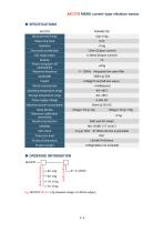
AKC378 MEMS current-type vibration sensor E.g: AKC378-02-A1: ±2g measure range /4~20mA output„
Open the catalog to page 4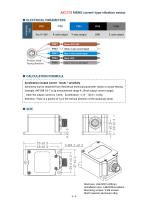
AKC378 MEMS current-type vibration sensor Acceleration=(output current -12mA) ^ sensitivity | Sensitivity can be obtained from theoretical technical parameter values or actual testing Example: AKF398-02-T (±2g measurement range 4-20mA output current range), when the output current is 13mA, Acceleration = (13-12)/4 = 0.25g Attention: There is a gravity of 1g in the vertical direction of the stationary state. Shell size: L55*W37*H29mm Installation size: L48xW28.6xH4mm Mounting screws: 3 M4 screws Shell material: aluminum alloy
Open the catalog to page 5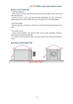
- Short-circuit the self-test wire (Self-Test) and the ground wire (GND), and the sensor will enter self-test mode. - At this time, the X, Y, and Z axis output terminals will generate ±1g, 10Hz square wave signals respectively to verify whether the sensor and output circuit are working properly. - After the self-test is complete, the self-test line must be left floating (disconnected from GND). - During normal operation, the self-test cable must be kept suspended; otherwise, measurement accuracy will be affected. - Do not short-circuit the self-test cable to the power supply (Vcc), as this may...
Open the catalog to page 6All SHENZHEN RION TECHNOLOGY CO.,LTD catalogs and technical brochures
 RION HDA436T TILT SENSOR
14 Pages
 RION SMI815 SMI825
5 Pages
 RION DMI850 inclinometer
9 Pages
 RION WCA300A
3 Pages
 RION PSI-25M
1 Page
 Rion inclinometer SDA118T
10 Pages
 SDA116T/SDA126T
16 Pages
 RION SDA116T/SDA126T-CAN OPEN
11 Pages
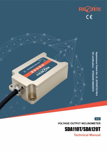 Rion SDA110T inclinometer
9 Pages
 Rion inclinometer SCA118T
10 Pages
 Rion inclinometer SCA116
16 Pages
 Rion inclinometer SCA110
10 Pages
 Rion inclinometer PCA826T
21 Pages
 Rion inclinometer MCA418T
2 Pages
 Rion inclinometer MCA416T
2 Pages
 Rion inclinometer MCA416LD
10 Pages
 Rion inclinometer MCA416L
10 Pages
 Rion inclinometer MCA416
2 Pages
 Rion inclinometer MCA410T
2 Pages
 Rion inclinometer MCA-85
12 Pages
 Rion inclinometer LCA318T
10 Pages
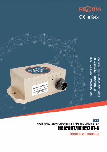 Rion HCA518T inclinometer
9 Pages
 Rion inclinometer HCA510T-N
11 Pages
 Rion inclinometer HCA510T
8 Pages
 Rion inclinometer HCA396B
11 Pages
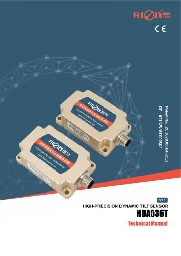 RION HDA536T INCLINOMETER
25 Pages
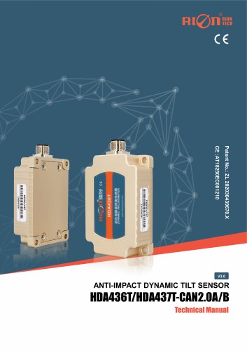 HDA437T/HDA437T-CAN2.0A/B
14 Pages
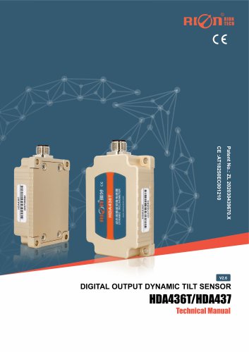 HDA437T/HDA437
25 Pages
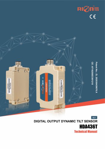 HDA436T
25 Pages
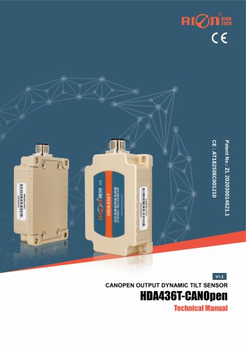 HDA436T-CANOpen
28 Pages
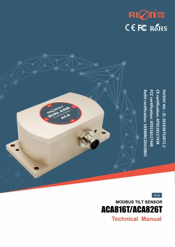 ACA816T/ACA826T
17 Pages
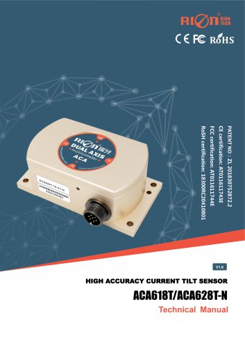 ACA618T/ACA628T-N
9 Pages
 Rion inclinometer ACA610T
9 Pages
 Rion electronic compass DDM350B
11 Pages
 Rion electronic compass DCM301B
11 Pages
 Rion electronic compass DCM250B
12 Pages
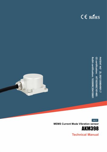 Rion AKM398 Vibration Sensor
6 Pages
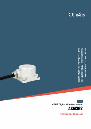 Rion AKM392 Vibration Sensor
15 Pages
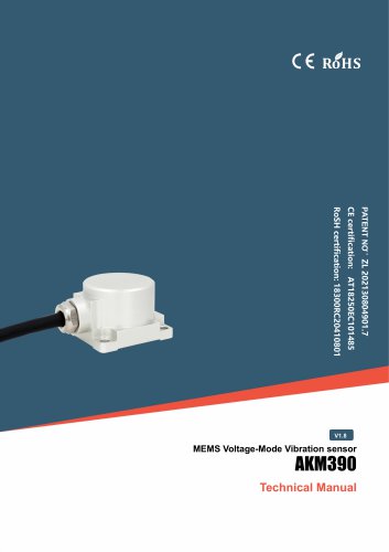 Rion AKM390 Vibration Sensor
6 Pages
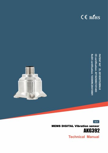 Rion Vibration Sensor AKG392
17 Pages



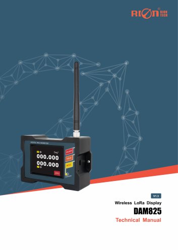
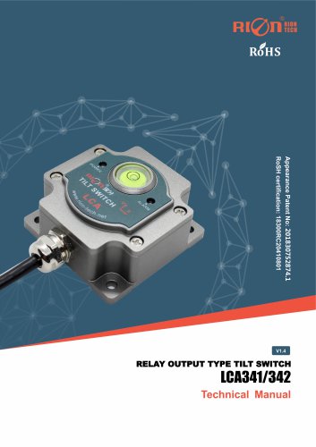
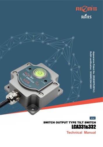
Archived catalogs
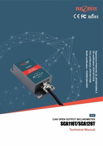
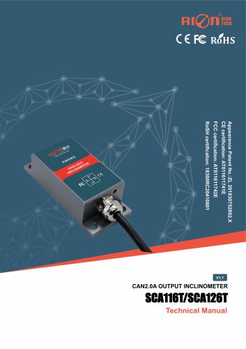 SCA116T/SCA126T
9 Pages
- LCD screen
- Industrial monitor
- Panel-mount screen
- Pressure probe
- High-brightness monitor
- RION inclinometer
- TFT-LCD monitor
- Analog pressure sensor
- RION digital inclinometer
- Stainless steel pressure sensor
- Relative pressure sensor
- RION 2-axis inclinometer
- RION MEMS inclinometer
- RION multi-axis inclinometer
- Absolute pressure sensor
- RION analog inclinometer
- Gas pressure sensor
- Sensitive element pressure sensor
- RION high-precision inclinometer
- Liquid pressure sensor