
- Catalogs
- ShenZhen INVT Electric Co., Ltd.
- MH800 Hydraulic Servo System


MH800 Hydraulic Servo System

MH800 Hydraulic Servo System
The MH800 series electro-hydraulic servo system is engineered for injection molding machines and hydraulic mechanical processes, emphasizing high-performance vector control for efficiency, energy conservation, and environmental protection. It supports centralized intelligent control and smart automation, ensuring stability and environmental tolerance.
The system is designed to minimize noise and electromagnetic interference, adapting to challenging conditions such as poor grid quality, temperature fluctuations, humidity, and dust. It offers real-time monitoring of motor and drive temperatures to ensure safe operation and extend system life, with power ranges from 4.4 kW to 75 kW.
The MH800 series features a three-phase full-wave rectifier and IGBT PWM control, supporting a maximum output frequency of 400 Hz and operating within a temperature range of -20 to +55°C. It includes multiple digital and analog signal inputs and outputs, with communication capabilities via CAN and RS485.
Various drive models support motor capacities from 4.4 kW to 75 kW, with specific rated output and input currents, maximum current outputs, and braking resistors. Naming conventions indicate power level, voltage input type, and communication type.
Installation dimensions and aperture sizes are specified for different drive models to ensure proper fit and compatibility.
Specifications for servo motors include casing length, flange diameter, weight, insulation class, and protection grade. Electrical parameters cover rated power, torque, current, voltage, and speed, complying with IEC61800-3 standards.
The document provides a layout of drive terminals, detailing connections and configurations for efficient system integration.
The document outlines technical specifications and wiring diagrams for the MH800 Hydraulic Servo System, detailing its components, configurations, and applications.
- LED Display and Operation Panel for user interaction.
- Various ports including CN3 for CAN/485 communication, CN1A for I/O output, CN1B for HMI interface, CN2 for encoder interface, and CN5 for I/O control.
- J9 switch for selecting pressure sensor type.
- Wiring diagrams emphasize using shielded cables for analog signals and twisted-pair shielded cables for encoder and communication lines to prevent signal interference.
- Power supply configurations for pressure sensors and internal power supply settings are detailed, including jumper settings for voltage adjustments.
- Single and multiple pump control systems are described, with diagrams illustrating the flow of instructions and pressure feedback mechanisms.
- Multi-mode control systems and compound mode configurations are explained, highlighting the use of master and slave nodes for efficient operation.
- Standard configuration tables list various system types, flow rates, pressures, and compatible pump and motor models.
- Guidelines for selecting pumps, motors, and drives based on system requirements are provided.
- The energy-saving rate of the servo hydraulic system is influenced by the dwell and cooling time in the molding cycle, with power consumption typically ranging from 20% to 80%.
- The MH800 Hydraulic Servo System is applicable in various machines such as injection molding, die casting, shoes manufacturing, bottle blowing, hydraulic presses, and silicone rubber machines.
Catalog excerpts
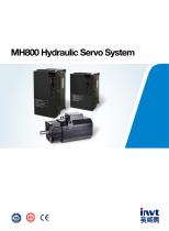
MH800 Hydraulic Servo System
Open the catalog to page 1
MH800 Hydraulic Servo System
Open the catalog to page 2
Product introduction MH800 series of electro-hydraulic servo system is designed base on study of injection molding machine and hydraulic mechanical technological process, which is type of upgraded series high performance hydraulic servo system. With advanced High performance vector control, its easily implement lean extraordinary quality of high efficiency, energy conservation and environmental protection; Abundant power and communication interface, easily to realize more centralized intelligent control devices network and smart automation production line. This type of hydraulic servo system...
Open the catalog to page 3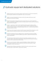
MH800 Hydraulic Servo System Hydraulic equipment dedicated solutions Meeting the demand of environment protection which focuses on low noise and weakening electromagnetic interference in the application sites for the customers. Adapt to worse grid, temperature ,humidity and dust with a better performance of antitripping and improved the reliability. Monitor the temperature change of the motor and drive all the way, real-time adjustment system overload limiter, guarantee the safe and stable operation of motor and drive, extending the service life of the system. Product’s power from 4.4 kW to 75...
Open the catalog to page 4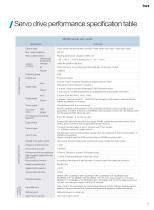
/ Servo drive performance specification tableMH800 hydraulic servo series Specification Control mode Max. output frequency Motor position sensor Use/storage temperature working Humidity condition Air Altitude Protection grade LED display panel and the keyboard External HMI Control mode Control input Instruction Three-phase full wave rectifier and IGBT PWM control sine wave current drive mode 400 Hz Rotating transformer, resolution 4096 / rev -20 ~ +55 °C (^45 °C derating use) / -20 ~ +85 °C =s95%RH (Shall not be dew) Indoor (not sun), no corrosive gas, flammable gas, oil and gas, no dust «2000m IP20...
Open the catalog to page 5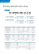
/ MH800 Hydraulic Servo System / Product description servo drivesSV-MH800-5R5-33-S 00© © ® @ © © Symbol Apply to motor capacity 4.4(kW) 5.5(kW) 7.5(kW) 11(kW) 15(kW) Rated output current 13A 18A 22A 26A 30A Rated input current 18A 24A 28A 32A 37A Maximum current output 25A 35A 46A 53A 64A
Open the catalog to page 6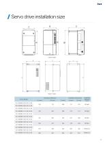
/ Servo drive installation size Drive Model
Open the catalog to page 7
/ MH800 Hydraulic Servo System Axis type P: Flat key N: Internal spline W: Male spline G: Smooth axis Z: Cone axis Internal used code Cooling mode F: Fan Cooling N: Nature Coolin Y: Liquid Cooling Rated torque (Not including the individual models) mM series motors code
Open the catalog to page 8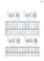
Model Size: K072F18C18P Model Size: K078F20C18P / K091F15C18P
Open the catalog to page 9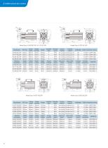
/ MH800 Hydraulic Servo System
Open the catalog to page 10
/ Drive terminal layout LED display Operation panel CN3 port: CAN/485 communication CN1A port: the I/O output CN1B port: HMI interface CN2 port: The encoder interface
Open the catalog to page 11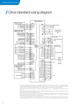
/ MH800 Hydraulic Servo System / Drive standard wiring diagram Servo driver Pressure sensor P ress u re feedback output Common line Mains input System controller Flow of instructions o- Common line l Analog output 2 Alarm reset Servo ready output O Alarm output Double displacement plunger pump Braking unit or braking resistor -°1 Motor three-phase input ft O T1 Temperature T2 detection signal Encoder signal Note 1: in the wiring diagram, the digital input signal using the system controller power to drive, CN5 connector’24V power from the external. The power of the pressure sensor can also be...
Open the catalog to page 12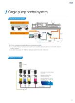
Single pump control system Single pump control system Single pump servo system Motor cable Power supply Other signals Speed feedback Pressure Servo system INVT offer complete servo electro-hydraulic combination products: 1. 4.4 ~ 75 kW of electro-hydraulic servo system can completely satisfy the amount of under 500 t injection molding machine; 2. Can drive the oil pump 16 ~ 160 ml/r, satisfy the system flow of 32 ~ 320 L/min. Multiple pump system CAN bus for communication between the controller Reasonable distribution of the master/slave pump work Maximum support 16 sets of pump work together,the...
Open the catalog to page 13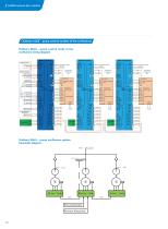
MH800 Hydraulic Servo System Ordinary Multi - pump control system of the confluence Ordinary Multi - pump control mode of the confluence wiring diagram Master servo driver Pressure sensor Pressure feedback output Common line Mains input Common line Driver enable Alarm reset 19 15 Servo ready output Alarm output 3 Pressure for output Double displacement plunger pump Wobble-plate output Three-phase AC power input 380V U Motor three-phase V input W Temperature detection signal R1 R2 Sin+ Encoder signal SinCos+ Cos- Temperature detection signal R1 R2 Sin+ Encoder signal SinCos+ CosFan power input...
Open the catalog to page 14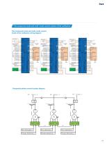
The compound mode and multi-mode control system of the confluence The compound mode and multi-mode control mode of the confluence wiring diagram Master servo driver Pressure sensor Pressure feedback output Common line Mains input Common line Analog output 1 Driver enable Alarm reset Servo ready output Alarm output 3 Pressure for output Double displacement plunger pump Wobble-plate output Common line Three-phase AC power input 380V Driver enable Temperature detection signal R1 R2 Sin+ Encoder signal SinCos+ Cos- Servo ready output Alarm output 3 Pressure for output Double displacement plunger...
Open the catalog to page 15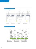
MH800 Hydraulic Servo System Multi-mode control system diagram Follow Unit Control Unit Slave Node Master Node C/D:Confluence/shunt signal S_RDY: Servo is ready Multi-mode control system diagram Flow Instruction 1 Pressure Instruction 1
Open the catalog to page 16
The naming rules of hydraulic configuration ® KINWAY ® System flow(L/min)
Open the catalog to page 17
/ MH800 Hydraulic Servo System flow (L/m in) x 1000 rev/min Speed : the smaller value of maximum speeds of motor and pump Known : maximum pressure and flow in hydraulic system Select a motor has the rated torque equals to half as maximum torque Known : maximum pressure and flow in hydraulic system Peak current(A)= rated current (A)x Max pressure (MPa) consistant working pressure (MPa) Known : maximum pressure and flow in hydraulic system Please consult with INVT engineers to get optimized system configuration.
Open the catalog to page 18All ShenZhen INVT Electric Co., Ltd. catalogs and technical brochures
 Goodrive20-LA series
10 Pages
 Goodrive20/Goodrive310 Series
16 Pages
 Goodrive20 Series
10 Pages
 GD170-PV Series
6 Pages
 GD27 Series Smart VFDs
15 Pages
 HMI Product Catalog
8 Pages
 STICK LOGGER
2 Pages
 XG50-70kW
1 Page
 Goodrive300 Series VFD
292 Pages
 Goodrive200A series
11 Pages
 AX Series
21 Pages
 Solar Pumping Controller
6 Pages
 Products catalogue
15 Pages
 EMI power filter
8 Pages
 About INVT
2 Pages
 INVT Album
2 Pages
 INVT products catalogue
12 Pages


- Digital I/O
- Servo-amplifier
- Battery charger
- Programmable logic controller
- Ethernet communication router
- On-line UPS
- Fieldbus servo-drive
- Frequency inverter
- Variable frequency drive
- IEC battery
- AC buffered power supply
- CE battery
- AC servo-amplifier
- Single-phase UPS
- Rectangular battery
- UPS with LCD display
- Solar DC/AC inverter
- Data communication router
- RS485 programmable logic controller
- 3-phase AC drive