
- Catalogs
- ShenZhen INVT Electric Co., Ltd.
- Goodrive300 Series VFD


Goodrive300 Series VFD

Goodrive300 Series VFD
The Goodrive300 series VFDs are high-performance vector drives for controlling asynchronous AC induction motors and permanent magnet synchronous motors. They use advanced vector control technology and a DSP control system to enhance reliability and performance, suitable for challenging environments.
This chapter stresses the importance of safety precautions to prevent injury or damage. It defines safety terms and states that the company is not liable for damages from ignoring these precautions.
Guidance is provided on unpacking, application confirmation, environmental considerations, installation confirmation, and basic commissioning for proper VFD setup and operation.
This chapter outlines the principles, specifications, nameplate details, model code, rated specifications, and structure diagram of the Goodrive300 series VFDs.
Details on mechanical installation, standard wiring, and layout protection are provided to ensure correct installation and operation.
This section explains the keypad layout, display, and operation procedures for effective control and monitoring of the VFD.
Comprehensive details on the function parameters of the Goodrive300 series are provided, allowing for customization and optimization of the VFD's performance.
Instructions for first powering on, vector control, SVPWM control, torque control, motor parameters, start-up and stop control, frequency setting, and various input/output configurations are covered.
This chapter provides information on alarm and fault indications, reset procedures, fault history, and solutions for common faults.
Guidance on maintenance intervals, cooling fan, capacitors, and power cable maintenance is provided to ensure long-term reliability.
An introduction to the Modbus protocol and its application in VFDs, along with RTU command codes and communication data illustrations, is included.
Additional information on extension cards, technical data, dimension drawings, peripheral options, and further resources is provided for comprehensive understanding and application of the VFD.
The document provides detailed instructions for the installation and connection of Variable Frequency Drives (VFDs) for different voltage levels, specifically 380V, 500V, and 660V. It includes connection diagrams for main circuits and control circuits, highlighting the importance of removing specific contact tags and labels to ensure proper connections.
For VFDs of 500V (≥22kW), it is necessary to remove the contact tag between P1 and (+) if connecting with a DC reactor. The document provides a connection diagram for VFDs of AC 3PH 520V (-15%)–690V (+10%), detailing optional parts like fuses, DC reactors, and braking units.
The document lists terminal names and their functions for different VFD voltage levels. It emphasizes the importance of proper grounding and the use of optional parts like braking resistors and DC reactors.
Instructions are provided for connecting input power cables, motor cables, and brake resistors. The document stresses the importance of fastening all cables securely.
Diagrams and descriptions are provided for control circuit terminals, including multi-function input terminals and relay outputs. The document explains the use of U-shaped short-circuit connectors for setting NPN or PNP modes.
The document outlines protection strategies for VFDs, input power cables, and motors against short-circuit situations and thermal overload. It advises on the use of fuses and thermal protection functions.
The document describes the keypad used for controlling the VFDs, including its keys, indicators, and display functions. It provides instructions for viewing and modifying function code settings through the keypad.
Recommendations include not using asymmetrically constructed motor cables, routing cables separately, and ensuring proper grounding techniques. It also advises against connecting supply power to VFD output terminals to prevent damage.
1. B Frequency: Sets the current frequency to B.
2. A+B Frequency: Sets the frequency to the sum of A and B.
3. A-B Frequency: Sets the frequency to the difference between A and B.
4. Max(A, B): Sets the frequency to the higher of A or B.
5. Min(A, B): Sets the frequency to the lower of A or B.
Note: The combination method can be adjusted via terminal function P5.
Allows setting frequency via keypad within the range of 0.00 Hz to the maximum frequency (P00.03).
Defines the time required for the VFD to speed up from 0Hz to maximum frequency and vice versa. Four groups of ACC/DEC times are available, selectable via P05.
0: Forward direction (default).
1: Reverse direction.
2: Prohibit reverse direction.
Defines the carrier frequency, affecting noise, leakage, and heating. High frequencies improve waveform but increase losses and interference. Default values depend on the model.
0: No operation.
1: Rotating autotuning for high accuracy.
2: Static autotuning for non-decoupled motors.
3: Partial static autotuning.
0: Invalid.
1: Valid throughout the procedure to stabilize output voltage.
0: No operation.
1: Restore default values.
2: Cancel fault record.
Start Mode (P01.00): Options include direct start, start after DC braking, and start after speed tracing.
Stop Mode (P01.08): Options include decelerate to stop and coast to stop.
Includes settings for motor type, rated power, frequency, speed, voltage, and current. Autotuning updates parameters for optimal performance.
- Motor Slip Compensation: The slip frequency is calculated using the formula △f=fb-n×p/60, where fb is the rated frequency, n is the rated speed, and p is the pole pair of the motor. The setting range is 0.0–200.0%.
- Vibration Control: Parameters P04.10 to P04.25 are used to manage vibration control at low and high frequencies for motors 1 and 2. Adjustments can prevent instability and overcurrent issues.
- V/F Curve Settings: Parameters P04.13 to P04.22 define the V/F curve settings for motor 2, allowing customization for different load requirements.
- Energy-Saving Operation: Parameter P04.26 allows for automatic energy-saving adjustments based on load conditions.
- Voltage Settings: Parameters P04.27 to P04.32 manage voltage settings, including maximum and minimum output voltages and voltage increase/decrease times.
- Input Terminals Configuration: Parameters P05.00 to P05.54 configure input terminals, including function selection, polarity, and delay settings. This section also covers analog input settings for AI1, AI2, and AI3.
- Output Terminals Configuration: Parameter P06.00 details the function selection for high-speed pulse output terminals.
- Adjust vibration control parameters to stabilize motor operation and prevent overcurrent.
- Utilize energy-saving operations for motors with light loads to optimize efficiency.
- Configure input and output terminals according to specific application needs to ensure proper VFD operation.
- Integral Adjustment (P09.06): Determines the strength of the change ratio during integral adjustment. Longer integral time results in stronger adjustment. Range: 0.00–10.00s.
- Sampling Cycle (P09.07): Defines the feedback sampling cycle. Longer cycles result in slower response. Range: 0.000–10.000s.
- Deviation Limit (P09.08): Sets the maximum deviation for PID system output. Range: 0.0–100.0%.
- Output Limits (P09.09 & P09.10): Define the upper and lower limits of PID adjustor output. Upper limit range: P09.10–100.0%, Lower limit range: -100.0%–P09.09.
- Feedback Offline Detection (P09.11 & P09.12): Sets detection value and time for feedback offline faults. Detection value range: 0.0–100.0%, Time range: 0.0–3600.0s.
- PID Adjustment (P09.13): Configures integral adjustment behavior and direction settings.
- Proportional Gain (P09.14): Sets the proportional gain at low frequency. Range: 0.00–100.00.
- ACC/DEC Time (P09.15): Defines the acceleration/deceleration time for PID commands. Range: 0.0–1000.0s.
- Output Filter Time (P09.16): Sets the filter time for PID output. Range: 0.000–10.000s.
- Simple PLC (P10.00): Configures the operation mode of the VFD after a cycle. Options include stopping, running at final value, or cycling.
- Memory (P10.01): Determines if the PLC retains memory after power loss.
- Multi-step Speed (P10.02–P10.33): Defines frequency and operation time for up to 16 stages. Negative values indicate reverse rotation.
- ACC/DEC Time (P10.34 & P10.35): Sets acceleration/deceleration times for steps 0–15 using binary and hexadecimal configurations.
- PLC Restart (P10.36): Configures restart behavior after a stop or fault.
- Time Unit (P10.37): Sets the time unit for multi-step operations (seconds or minutes).
- Phase Loss Protection (P11.00): Enables or disables input and output phase loss protection.
- Frequency Decrease at Power Loss (P11.01 & P11.02): Configures frequency decrease behavior during sudden power loss.
- Overvoltage Stall Protection (P11.03 & P11.04): Enables protection against overvoltage stalls and sets voltage protection levels.
- Current Limit Actions (P11.05 & P11.06): Configures actions to prevent overcurrent faults during acceleration.
- Overload Pre-alarm (P11.08–P11.10): Sets parameters for overload pre-alarm detection and response.
- Underload Pre-alarm (P11.11 & P11.12): Configures detection and response for underload conditions.
- Output Terminal Actions (P11.13): Defines actions for fault output terminals during undervoltage and reset.
- Speed Deviation Detection (P11.14 & P11.15): Sets parameters for detecting speed deviations.
- Automatic Frequency Decrease (P11.16): Ensures rated output torque during voltage drops.
- Motor Type (P12.00): Selects between asynchronous and synchronous motor types.
- Rated Parameters (P12.01–P12.05): Sets rated power, frequency, speed, voltage, and current for asynchronous motor 2 based on the motor's nameplate.
The document outlines the function parameters for the Goodrive300 Series Variable Frequency Drive (VFD). Key specifications include Ethernet communication settings, such as communication speed options (10M/100M full or semi-duplex) and IP address configuration. The IP address is set using parameters P16.01 to P16.04, and the subnet mask is configured with P16.05 to P16.08. Gateway settings are defined by P16.09 to P16.12.
Parameters P17.00 to P17.39 cover various monitoring functions, displaying real-time data such as set frequency, output frequency, voltage, current, motor speed, torque, and more. These parameters help in assessing the operational status and performance of the VFD.
Chapter 7 provides instructions for basic operations, including initial power-on procedures and checks. It emphasizes ensuring correct wiring and power compatibility between the motor and VFD. The section also details the steps for first-time operation, including motor type selection, autotuning, and setting running frequency and speed control modes.
The document explains vector control, a method used to manage asynchronous motors by decoupling exciting and torque currents. This section highlights the importance of accurate motor parameter input and autotuning for optimal vector control performance. It also describes the internal function modules and control calculations involved in vector control.
Various function codes are provided for configuring the VFD, including speed control modes (P00.00), motor parameter autotuning (P00.15), and motor type (P02.00). The document also covers torque control settings and compensation coefficients for vector control.
Users are advised to follow specific procedures for parameter input and autotuning to ensure high performance and reliability. The document suggests using caution when configuring vector control parameters due to their complexity.
The document outlines various settings and parameters for the Goodrive300 Series Variable Frequency Drives (VFDs). Key settings include frequency limits for forward and reverse rotation, torque limits, and voltage settings. The VFDs support multiple communication methods such as Modbus, PROFIBUS/CANopen, and Ethernet.
Instructions are provided for setting up torque control and speed control modes. The document details how to configure the V/F curve settings, including linear, multi-dots, and power-based curves. It also explains the torque boost function and energy-saving running mode.
Recommendations are given for selecting V/F curves based on load types, such as constant torque or decreasing torque loads. The document advises caution when setting parameters to avoid damage to the VFD.
The Goodrive300 series VFDs offer SVPWM control for applications not requiring high control accuracy and support multiple motors. They include features like torque boost, energy-saving operation, and vibration control.
Safety warnings are included regarding the risk of physical accidents during autotune and the potential for electric shock if the motor is touched during static autotune.
- Max Output Frequency: 50.00Hz to 400.00Hz.
- Frequency Commands: Multiple sources including keypad, AI inputs, PLC programs, PID control, and communication protocols like Modbus and Ethernet.
- Switching Channels: Instructions for switching between A and B channels using multi-function terminals.
- Frequency Adjustment: Use of UP (10) and DOWN (11) terminals to quickly adjust frequency settings.
- Frequency Limits: Upper and lower frequency limits can be set within specified ranges.
- Analog Inputs: Three analog input terminals (AI1, AI2, AI3) with configurable voltage/current settings and filtering options.
- Digital Inputs: Eight programmable digital input terminals with various selectable functions.
- Analog Outputs: Two terminals for output signals proportional to motor speed, frequency, current, torque, etc.
- Digital Outputs: High-speed pulse output options for various operational feedbacks.
- Ensure correct parameter settings for desired operational outcomes.
- Regularly verify input and output configurations to maintain system efficiency.
- Multi-function terminals have specific valid and invalid states depending on the channel settings.
- Two different multi-function terminals cannot be set to perform the same function.
- Control Functions: The VFD supports multiple control functions including forward and reverse running, jogging, coast to stop, fault reset, and operation pause. Each function is associated with specific terminal settings and parameters.
- Frequency Settings: The document details how to adjust frequency settings using external terminals. It includes instructions for increasing, decreasing, and clearing frequency settings, as well as switching between different frequency channels.
- Multi-step Speed Control: The VFD can be configured for multi-step speed control using digital terminal combinations. This allows for precise speed adjustments across 16 stages.
- ACC/DEC Time Selection: Users can select acceleration and deceleration times through terminal combinations, providing flexibility in motor control.
- PLC and PID Control: The VFD supports simple PLC operations and PID control, with options to pause or reset these functions as needed.
- Terminal Function Selection: The document provides a comprehensive list of terminal functions, allowing users to customize the VFD's response to various inputs.
- Digital Output Configuration: The VFD includes programmable digital output terminals, which can be configured for various operational signals such as running status, fault conditions, and frequency arrival.
- P05.00 - P05.31: These parameters define input terminal functions, including control modes and delay settings.
- P06.00 - P06.13: These parameters configure digital output functions, including output type and delay times.
- Phase Loss: Issues with input phases R, S, T. Check input power and distribution.
- Output Phase Loss: U, V, W phase loss or asymmetrical load. Inspect output distribution, motor, and cables.
- Rectifier Module Overheated (OH1): Caused by blocked air ducts, fan damage, high ambient temperature, or prolonged overload. Solutions include clearing vents, replacing fans, and reducing ambient temperature.
- Inverter Module Overheated (OH2): Similar causes and solutions as OH1.
- External Fault (EF): Triggered by external device input issues. Check external device connections.
- Communication Faults (CE, E-DP, E-NET, E-CAN): Issues with baud rate, wiring, address settings, or interference. Solutions involve checking settings, connections, and reducing interference.
- Current-Detecting Fault (ItE): Poor control board connection or broken components. Check connectors and replace faulty parts.
- Motor Autotuning Fault (tE): Mismatch between motor and VFD capabilities or incorrect parameter settings. Adjust VFD mode and parameters.
- EEPROM Operation Fault (EEP): Parameter read/write errors or EEPROM damage. Reset or replace control panel.
- PID Feedback Fault (PIDE): Issues with PID feedback signal or source. Verify signal and source.
- Braking Unit Fault (bCE): Faulty braking circuit or insufficient resistor. Check and replace components.
- Running Time Arrival (END): VFD exceeds set running time. Adjust settings with supplier.
- Electrical Overload (OL3): Overload pre-alarm triggered. Check load and alarm settings.
- Keypad Communication Fault (PCE): Poor keypad wire connection or interference. Check wires and environment.
- Parameter Uploading/Downloading Fault (UPE, DNE): Connection issues or data storage errors. Verify connections and hardware.
- Grounding Shortcut Faults (ETH1, ETH2): Short circuit with ground or detection circuit fault. Check motor connections and parameters.
- Speed Deviation Fault (dEu): Heavy load or stalled motor. Check load and control parameters.
- Maladjustment Fault (STo): Incorrect synchronous motor parameters. Verify settings and increase detection time.
- Electronic Underload Fault (LL): Underload pre-alarm triggered. Check load and alarm settings.
- Motor Does Not Work: Check power, contactor, voltage, and motor configuration.
- Motor Vibration: Verify motor parameters, load, and frequency settings.
- Overvoltage: Ensure voltage range, ACC/DEC time, and load conditions are correct.
- Undervoltage: Check power supply, switches, and contactors.
- Abnormal Motor Heating: Verify motor parameters, load, and frequency settings.
- VFD Overheating: Clean heat sink, reduce load, and check ambient conditions.
- Motor Stall During ACC: Check ACC time, torque boost, and load conditions.
- Overcurrent: Verify V/F control parameters, load, and motor connections.
- Maintenance Intervals: Routine checks on environment, voltage, keypad, and main circuit.
- Visual Inspections: Check for damage, dust, and proper connections.
- Capacitors: Measure static capacity using instruments. Ensure it is at least 85% of the original value. Reform DC bus capacitors if stored for long periods, following specific charging procedures based on storage duration.
- Resistors: Check for overheating, replacement, and splitting. Ensure resistors are within ±10% of the standard value.
- Transformers and Reactors: Check for abnormal vibration, noise, and smell.
- Electromagnetic Contactors and Relays: Ensure no vibration noise and that contactors are in good condition.
- Control Circuit PCB and Plugs: Check for loose screws, contactors, and signs of overheating or damage.
- Cooling System: Inspect cooling fans for noise, vibration, and overheating. The VFD cooling fan has a minimum lifespan of 25,000 hours.
- Stop the VFD and disconnect from power.
- Remove the fan cable and fan.
- Ensure the fan's wind direction matches the VFD.
- Restore power.
- Modbus Protocol: Used for master-slave communication via RS485 interface. Supports ASCII and RTU modes.
- RS485 Interface: Uses differential transmission with twisted pairs. Recommended to use shielded cables for remote communication.
- Single and Multi-Application: Describes connection setups for single and multiple VFDs using RS485, including chrysanthemum and star connections.
- RTU Mode: Provides a detailed format for RTU communication frames, emphasizing continuous data flow and error detection.
- 03H: Reads up to 16 words from the VFD.
- 06H: Writes a single word to the VFD.
- 08H: Used for diagnostics and returns inquiry information.
- 10H: Allows continuous writing of data to the VFD.
- State Definitions: Various states such as POFF, pre-exciting, and operational readiness are defined with specific bit configurations.
- Fault Codes: Fault codes are provided for diagnosing issues, with specific codes indicating illegal commands, data address errors, and operation failures.
- Parameter Settings: Parameters such as operation frequency, bus voltage, output voltage, and current are defined with specific ranges and units.
- Fieldbus Scale: Communication data is expressed in hexadecimal, with fieldbus ratio values used to convert non-integer values to integers.
- Fault Message Response: The document outlines how the VFD responds to faults, including illegal commands and data frame errors.
- Command Examples: Examples of reading and writing commands are provided, illustrating how to set parameters like running command channels and output frequency.
- Ensure correct parameter settings for successful VFD operation.
- Use the provided fault codes to diagnose and resolve communication issues.
- Follow the examples for command usage to effectively control the VFD.
The document outlines the communication protocols for the Goodrive300 Series VFD, highlighting issues such as mismatched baud rates and incorrect RS485 bus connections. It emphasizes the importance of correct terminal board connections to ensure proper communication.
The document provides a detailed description of extension cards used in Goodrive300 series VFDs, focusing on the PROFIBUS extension card. PROFIBUS is an international fieldbus standard used for data exchange in automation, supporting up to 127 nodes with repeaters.
The PROFIBUS extension card, EC-TX-103, connects VFDs to the PROFIBUS network, allowing control commands, speed signals, and parameter modifications. It supports PROFIBUS-DP protocol and uses twisted-pair or fiber optic cables for data transmission.
The document details the mechanical and electrical installation of the EC-TX-103 card, including ambient conditions, node address selection, and bus terminal settings. It provides guidelines for bus net connection and emphasizes the importance of grounding and shielding in high electromagnetic environments.
A table outlines the relationship between transmission rates and maximum cable lengths, with rates ranging from 9.6 kbps to 12 Mbps. The document also discusses the use of optical fibers for high-speed transmission in interference-prone environments.
The configuration of the master station and VFD is crucial for communication. Each PROFIBUS device requires a GSD file to describe its characteristics. The document provides configuration parameters for the EC-TX-103 card, including module type, node address, and baud rate settings.
PROFIBUS-DP enables rapid data exchange between master and slave devices. The document describes the data structures used in communication, including parameter identification and process data areas. Control and state words are used for communication between the master station and VFD.
The document outlines the setup and specifications for using PROFIBUS/CANOPEN control with a Variable Frequency Drive (VFD). The communication module must be configured as a VFD controller. The actual value is a 16-bit word containing converter operation information, with monitoring capabilities defined by VFD parameters.
The control word is the first word of the PZD task message, with different definitions for the PWM rectifier regenerative part and the inverter part. The document provides a detailed table for the Goodrive300 series, listing various command bytes and their functions, such as forward running, reverse running, and fault reset.
The reference value spans from the 2nd to the 12th word of the PZD task message, with settings for frequency, PID, torque, and more. The document provides a detailed table of functions and their corresponding bit settings.
The state word (SW) is the first word of the PZD response message, detailing the VFD's operational state, such as running, fault, or pre-exciting state. The document includes a table for the Goodrive300 series, explaining each bit's function.
The PKW area describes the parameter identification interface, crucial for parameter transmission between communication partners. The document explains the structure and function of the PKW area, including task requests and responses.
The EC-TX-103 communication card includes fault display LEDs to indicate online/offline status and configuration errors.
The document provides technical specifications, including VFD ratings, derating factors for temperature, altitude, and carrier frequency, and grid specifications. It also covers motor connection data, EMC compatibility, and applicable standards.
Derating is necessary if the ambient temperature exceeds 40°C, altitude exceeds 1000 meters, or the switching frequency changes. Specific derating coefficients are provided for temperature and altitude.
The document specifies grid voltage ranges, short-circuit capacity, and motor connection data, including motor type, voltage, frequency, and carrier frequency.
The VFD complies with several standards, including EN ISO 13849-1 and IEC/EN 60204-1, ensuring safety and compatibility.
The document outlines various international and national standards applicable to adjustable speed electrical power drive systems, including IEC/EN 62061, IEC/EN 61800-3, IEC/EN 61800-5-1, IEC/EN 61800-5-2, and GB/T 30844 series. These standards cover safety, EMC requirements, and technical conditions for variable-frequency adjustable-speed equipment.
CE marking indicates compliance with European directives on low voltage and electromagnetic compatibility (EMC). The EMC product standard EN 61800-3 specifies requirements and test methods for VFDs, ensuring they do not exceed electromagnetic disturbance limits and function properly in environments with electromagnetic interference.
VFDs are categorized based on their application environments and voltage ratings. Categories include C1 for civilian environments, C2 for specialized installations, C3 for non-civilian environments, and C4 for high voltage or current applications. Each category has specific installation and compliance requirements.
The document provides detailed dimension drawings for the installation of Goodrive300 Series VFDs, including wall, flange, and floor installations for various voltage and power ratings. It specifies dimensions, installation holes, and weights for different models.
Guidance is provided on selecting and installing peripheral components such as breakers, input reactors, DC reactors, braking units, and filters. These components help manage power factor, electromagnetic interference, and regenerative energy.
The document emphasizes the use of shielded cables for power and control connections to meet EMC standards. It specifies the use of symmetrical shielded cables for motor connections and provides guidelines for control cable configurations to minimize electromagnetic interference.
The document includes safety notes on installation practices, emphasizing the need for specialized personnel for certain installations and the importance of adhering to local regulations for cable dimensions and power supply compatibility.
The document outlines the specifications for various models of Goodrive300 Series Variable Frequency Drives (VFDs) across different voltage ranges: AC 3PH 380V(-15%)–440V(+10%), AC 3PH 380V(-10%)–550V(+10%), and AC 3PH 520V(-15%)–690V(+10%). It includes recommended cable sizes, terminal screw types, and tightening torques for each model.
1. Insulation Checking: Ensure the motor cable is connected to the motor and disconnected from the drive output terminals. Measure insulation resistance using a 500 V DC measuring voltage.
2. Breaker and Electromagnetic Contactor: Install a manually manipulated molded case circuit breaker (MCCB) between the AC power supply and VFD. The breaker should be 1.5 to 2 times the rated current of the VFD. An electromagnetic contactor can be configured to control the main circuit power.
1. Cable Routing: Motor cables should be routed away from other cables to reduce electromagnetic interference. Control cables should cross power cables at a 90-degree angle.
2. Reactors: Use AC reactors on the input side to prevent damage from high grid voltage. Output reactors are recommended when the VFD-to-motor distance exceeds 50 meters.
The document includes detailed tables listing the recommended cable sizes, terminal screws, tightening torques, and accessory specifications for each VFD model. It also provides specifications for input, DC, and output reactors.
- Ensure compliance with local regulations when checking insulation conditions.
- Use appropriate accessories based on market conditions, avoiding lower value options.
- For distances over 100 meters between VFD and motor, consult technical support for reactor selection.
The document outlines the specifications for the Goodrive300 Series VFDs, including various models and their corresponding input and output reactors. The rated derate voltage for input reactors is 2%±15%, and for output reactors, it is 1%±15%. The power factor on the input side is above 90% after installing a DC reactor.
Instructions are provided for connecting J10 for VFDs of 380V, with specific guidelines for different power ratings. The document advises on disconnecting J10 in certain situations, such as when using an IT grid system or if leakage protection issues arise.
The document emphasizes the importance of using interference and noise filters to reduce VFD interference and radio noise. It provides detailed instructions on selecting and installing filters based on voltage and current ratings.
Guidelines for selecting braking components are provided, including the importance of configuring brake components to prevent overvoltage faults. The document specifies the use of brake resistors and units, with detailed tables for selecting appropriate resistors based on brake torque and usage.
Safety instructions highlight the need for trained professionals to handle installation and operation. Specific warnings are given regarding the connection of brake resistors and units, emphasizing the importance of correct wiring to prevent damage and fire hazards.
The document provides contact information for product queries and feedback on manuals. It also directs users to the INVT website for additional resources and documentation.
Catalog excerpts
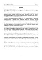
Preface Thanks for choosing our products. Goodrive300 series variable-frequency drives (VFDs) are high-performance open loop vector VFDs for controlling asynchronous AC induction motors and permanent magnet synchronous motors. Applying the most advanced non-velocity sensor vector control technology which keeps pace with the leading international technology and DSP control system, our products enhance their reliability, environmental adaptability, and customized and industrialized design with more optimized functions, more flexible application and more stable performance. The control performance...
Open the catalog to page 2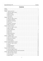
Contents Preface ···························································· i ···························································· Contents ···························································· ···························································ii Chapter 1 Safety precautions ··············································1 ············································· 1.1 What this chapter contains ·········································1 ········································ 1.2 Safety definition ················································1 ···············································...
Open the catalog to page 3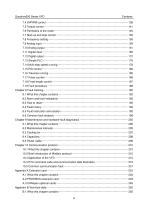
7.4 SVPWM control ·············································· 136 ·············································· 7.5 Torque control ··············································· 141 ··············································· 7.6 Parmeters of the motor ·········································· ········································· 145 7.7 Start-up and stop control ········································· ········································ 150 7.8 Frequency setting············································· 155 ············································· 7.9 Analog input...
Open the catalog to page 4All ShenZhen INVT Electric Co., Ltd. catalogs and technical brochures
 Goodrive20-LA series
10 Pages
 Goodrive20/Goodrive310 Series
16 Pages
 Goodrive20 Series
10 Pages
 GD170-PV Series
6 Pages
 GD27 Series Smart VFDs
15 Pages
 HMI Product Catalog
8 Pages
 STICK LOGGER
2 Pages
 XG50-70kW
1 Page
 Goodrive200A series
11 Pages
 AX Series
21 Pages
 Solar Pumping Controller
6 Pages
 MH800 Hydraulic Servo System
24 Pages
 Products catalogue
15 Pages
 EMI power filter
8 Pages
 About INVT
2 Pages
 INVT Album
2 Pages
 INVT products catalogue
12 Pages


- Digital I/O
- Servo-amplifier
- Battery charger
- Ethernet communication router
- On-line UPS
- Fieldbus servo-drive
- Frequency inverter
- Variable frequency drive
- IEC battery
- AC buffered power supply
- CE battery
- AC servo-amplifier
- Single-phase UPS
- Rectangular battery
- UPS with LCD display
- Solar DC/AC inverter
- Data communication router
- RS485 programmable logic controller
- 3-phase AC drive