- Catalogs
- Shenzhen Inovance Technology Co., LTD
- IS580 series AC Drive


- Products
- Catalogs
- News & Trends
- Exhibitions
IS580 series AC Drive
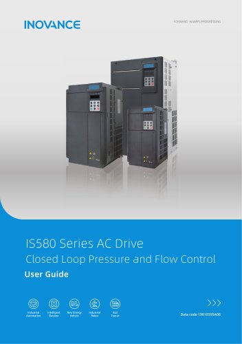
IS580 series AC Drive
This section underscores the importance of electrical safety when handling servo drives, highlighting risks such as electrical shock. It mandates that only qualified personnel should manage the equipment and stresses the need for proper machine/system design and safety assessments. Requirements for electrical installation include using appropriate earthing conductors and residual current devices to mitigate leakage current risks. Compliance with relevant safety standards and directives is mandatory.
Nameplate and Designation Rule: Details on the model designation for the IS580 series hydraulic servo drive are provided, including input/output specifications and manufacturer details.
General Specifications: The servo drive comes in various models with different frame sizes and power ratings. Specifications cover voltage class, rated power, output current, carrier frequency, overload capacity, and enclosure type. Dimensions for each frame size and braking resistor requirements are outlined.
Terminal Description: Describes the terminals for the main circuit of various IS580 models, including diagrams for terminal configurations and warnings against incorrect usage.
Provides an overview of the operating panel, detailing parameter operations and navigation for effective use.
Hydraulic Application Setup Flowchart: A flowchart guides users through the setup process for hydraulic applications, ensuring efficient configuration.
Introduction: Introduces the parameter list, including hydraulic control, basic control, and monitoring parameters, crucial for understanding the drive's functionality and performance monitoring.
Servo Fault Codes and Solutions: Provides a comprehensive list of fault codes with solutions for common issues, essential for diagnosing and resolving operational problems.
Servo Common Symptoms and Diagnostics: Outlines common symptoms of servo issues and diagnostic procedures to identify and rectify problems.
Designation Rules: Details on the designation rules for the ISMG servo motor, including physical appearance, mounting dimensions, and wiring instructions.
Lists certification marks and standards compliance, including CE, UL, and RoHS directives, emphasizing adherence to EMC installation requirements and European standards.
Outlines connections for a three-phase power supply and motor, detailing terminals for power supply and motor connections, and instructions for braking units and resistors.
Includes terminals for digital and analog inputs/outputs, internal power supplies, and jumper settings for voltage/current outputs.
Details the Resolver PG Card S58-PG-B1 with terminal functions and troubleshooting guidance for common issues.
Describes the MD38PGMD card with terminal functions, DIP switch settings, and indicator descriptions.
Features indicators and keys for controlling the servo drive, explaining the function of each key.
Parameters are organized into function code groups for basic control, hydraulic control, and status monitoring, with a flowchart for quick setup.
Provides detailed technical specifications and procedures for configuring and operating a hydraulic control system, including auto-tuning, hydraulic control mode selection, parameter settings, and backup operations.
Outlines three auto-tuning options for motor control, emphasizing the importance of performing auto-tuning without load.
The system can be set to various hydraulic control modes, automatically adjusting certain parameters.
Key parameters include maximum rotational speed, system hydraulic pressure, and pressure feedback limits, with default values and ranges provided.
Details the configuration of digital inputs for various functions, each with a specific setting range.
AI inputs are configured for pressure command, flow command, and pressure feedback, with specified voltage ranges.
Parameters like maximum reverse motor speed and minimum flow are set to maintain system stability.
Guidelines for setting proportional gain, integral time, and derivative time for hydraulic pressure control.
Advises users to back up parameters after setup using the FP-05 function.
Provides a comprehensive list of parameters categorized into groups such as flux weakening control, PG card settings, and basic hydraulic control.
Details various settings, ranges, units, defaults, and properties for different control groups, organized into sections like Basic Control, Motor Parameters, Vector Control, and more.
Provides a guide for troubleshooting various faults in a motor control system, including fault names, possible causes, and recommended solutions.
Addresses specific types of faults such as communication, relay, sensor, motor, drive, parameter, calibration, overvoltage, undervoltage, mechanical, and load faults, with solutions provided.
Includes flowcharts and diagrams for diagnostic procedures for specific faults.
Covers common symptoms like no display at power-on, with solutions provided.
Common issues include damaged components and poor connections, with solutions involving contacting Inovance and replacing faulty parts.
Includes models with specific designations, motor duty types, physical appearance, and mounting dimensions.
Emphasizes proper wiring and connection guidelines to avoid damage.
Document revisions from 2016 to 2023 include updates on firmware versions and certifications.
Catalog excerpts
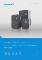
FORWARD, ALWAYS PROGRESSING IS580 Series AC DriveClosed Loop Pressure and Flow Control User Guide Intelligent New Energy Elevator Vehicle
Open the catalog to page 1
Safety Information and Precautions Safety Information and Precautions This guide is packaged together with the product. It contains basic information for quick start of the drive. For safety and more information, please refer to IS580 Servo Drive Advanced User Guide, which can be Downloaded on website: http://www.inovance.cn. Electrical Safety Machine/System Design and Safety of Personnel Extreme care must be taken at all times when working with the servo drive or within the area of the servo drive. The voltages used in the servo drive can cause severe electrical shock or burns and is potentially...
Open the catalog to page 3
Safety Information and Precautions Ensure the protective earthing conductor complies with technical standards and local safety regulations. Because the leakage current exceeds 3.5 mA in all models, IEC 61800-5-1 states that either the power supply must be automatically disconnected in case of discontinuity of the protective earthing conductor or a protective earthing conductor with a cross-section of at least 10 mm2 (Cu) or 16 mm2 (Al) must be used. Failure to comply may result in death or serious injury. When using an earth leakage circuit breaker, use a residual current operated protective...
Open the catalog to page 4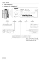
Note (a): The model number may include a suffix "XXXXXXXXXX", Where "XXXXXXXXXX" can be blank or combination of any alphanumeric and/or symbols that represents customer identity.
Open the catalog to page 5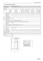
(1) the dimensions are shown below.
Open the catalog to page 6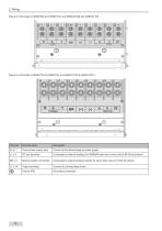
2 Wiring Figure 2-3 Terminals of IS580T080 and IS580T100, and IS580-2T080 and IS580-2T100 Terminal name Three-phase supply input Connect to the three-phase ac power supply. Connected to external braking unit (MDBUN) with servo drive units of 90 kW and above. Braking resistor connection Connected to external braking resistor for servo drive units of 75 kW and below. Output terminals Connect to a three-phase motor. Grounding connection.
Open the catalog to page 9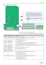
AI3 input jumper, voltage input as default QIQQII AO2 output jumper, voltage output as default OlO OH AO1 output jumper, voltage output as default DI power supply source jumper(internal/external), internal as default
Open the catalog to page 10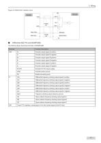
Figure 2-5 S58-PG-B1 interface circuit The following figure describes terminals of MD38PGMD
Open the catalog to page 12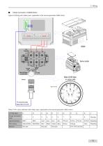
Cable Connector of ISMG Motor Figure 2-6 Wiring with military spec. (applicable to the second generation ISMG motor) Servo motor Encoder cable Male of Mil Spec on motor side Male of Mil Spec on motor side PG connecting cable Model: S58-L-P31-XXX Table 2-4 Pin colour definition with military spec. (applicable to the second generation ISMG motor) 17P Mil Spec. Signal Definition Wire Colour
Open the catalog to page 14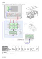
Figure 2-7 Wiring without military spec. (applicable to the first generation ISMG motor) COS+ SIN- SIN+ EXC- EXC+ KTY- KTY+ PTC- PTC+ COSBBBB- GND VCC Yellow Red/ Black Red Blue Yellow /White White COS+ SIN- SIN+ EXC- EXC+ KTY- KTY+ PTC- PTC+ COSBBBB- GND VCC Black Yellow Yellow/ Red/ White White First generation servo motor control cable interface board PG connecting cable Model: S58-L-P30-xxx Table 2-5 Pin colour definition without military spec. (applicable to the first generation ISMG motor) D-type Connector 9-pin Signal Definition Wire Colour 2.3 Wiring Please refer to the fold-out at the...
Open the catalog to page 15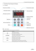
3 Operating Panel (Keypad & Display) Command source indicator Running direction indicator Running status indicator Menu mode selection key Other status indicator Parameter unit indicator Increment key Confirm key Shift key Decrement key Stop/Reset key There are four red led status Indicators at the top of the operating panel.
Open the catalog to page 16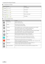
3 Operating Panel (Keypad & Display)
Open the catalog to page 17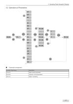
3 Operating Panel (Keypad & Display) ■ Parameter arrangement Function Code Group
Open the catalog to page 18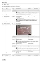
1: restore factory parameters Note: usually users have no idea what parameters have been changed, so it’s seriously recommended to restore parameters to default at the beginning of commissioning. Motor nameplate
Open the catalog to page 19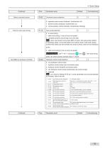
Select command source Command source selection
Open the catalog to page 20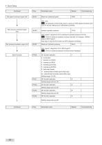
Set speed command upper limit
Open the catalog to page 21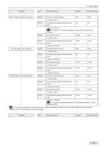
Set AI1 range: pressure command Note|: AI 1 is fixed as pressure command input, AI2 is fixed as speed/flow command input, and AI3 is fixed as pressure sensor feedback input. This configuration can’t be changed!
Open the catalog to page 22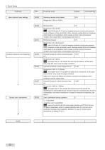
other hydraulic basic settings pressure response commissioning Backup user’s parameters
Open the catalog to page 23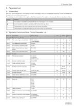
Groups F and A include basic and hydraulic function parameters. Group U includes the monitoring function parameters and extension card communication parameters. The parameter description tables in this chapter use the following symbols. The symbols in the parameter table are described as follows:
Open the catalog to page 24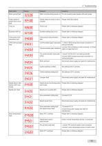
6 Troubleshooting Fault name Motor ground fault Motor runs fast during power on Do not connect power supply until motor stops Output phase to phase short-circuit fault Output phase to phase is shortcircuited Please check the outputs Please refer to following diagram Business setting time is out Please refer to following diagram Overcurrent multi prevention fault Overcurrent multi prevention fault Please refer to following diagram Communication gets interrupted 1. check if BUS wirings have loose connection or wrong connection Commnunication gets interfered 2.check if BUS shielding is well connected,...
Open the catalog to page 44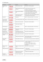
Fault name Pressure sensor fault Pressure sensor is faulty Please refer to following diagram EH6.01 Motor rotor gets locked or pump gets stuck 1 .check if rotor can be turned by hand 2. check if F2-10 sets properly 3. check if auto tuning can be conducted Pressure sensor calibration fault 1 .check if pressure feedback is around zero 2. check if pressure sensor is well connected Pressure sensor output is beyond setting range Pressure sensor output is beyond setting range [A3-55, A3-56], please check the sensor Slave fault Refer to <multi pumps solution> in User manual Communication address conflict...
Open the catalog to page 45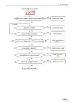
Overcurrent during acceleration Output phase to phase or phase to ground short-circuit? No V/F control auto tuning succeeds? Yes acceleration time is too short? N o VF control, check if torque boost or V/F curve is set properly Conduct auto tuning Adjust torque boost or V/F curve No power supply is abnormal? Adjust the power supply No Restarted the motor before it stopped? Restart motor until it stops No Shock load during acceleration? Remove shock load No Use a higher rating drive
Open the catalog to page 46All Shenzhen Inovance Technology Co., LTD catalogs and technical brochures
 Inovance Robot Selection
26 Pages
 Inovance Robot
2 Pages